Overview – Meinberg VME31 User Manual
Page 6
6
Overview
The radio remote clock DCF77 VME31 receives the time marks from DCF77 and
makes the decoded time available to VME bus systems. The clock is designed on a 3U
board (euro card size), so it can be used in either 3U systems or 6U systems. An
external ferrit antenna passes the signal from DCF77 to the on-board long wave
receiver. The demodulated time marks are decoded by the clock´s microprocessor. If
no errors are detected in the current time message, an additional plausibility check
against the previous time message is performed. If that plausibility check passes, too,
the battery buffered real time clock on the board is synchronized corresponding to the
decoded time and date.
Software running on the computer can read out the date/time/status and some more
information from the board's dual port RAM which is updated in 10ms intervals. The
dual port RAM can be configured by a block of jumpers to be mapped to any 1k
boundary in the system's A16 address range. It can be accessed using either Short
Supervisor I/O (2Dh) or Short Non-Priviledged I/O (29H). The radio remote clock can
generate cyclic interrupts at one of the levels IRQ1 through IRQ7 at a rate of 10ms,
100 ms, 1s, 10s, 60s, or 1h.
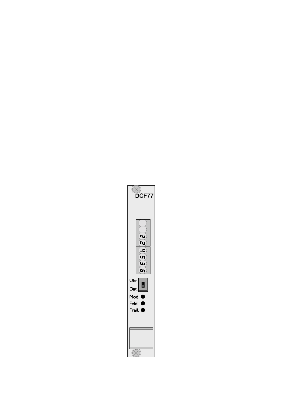
Frontansicht