Methven Kiri User Manual
Page 2
2
7
Index
Box Contents ...................................................................................
Site Installation Conditions ..............................................................
Operating Requirements ................................................................
Installation .......................................................................................
Maximum Temperature Setting and Adjustment .............................
Parts Reference Drawing ................................................................
Maintenance ...................................................................................
Product Care ...................................................................................
Warranty
................................................................................................................
Box Contents
Site Installation Conditions
Prior to installing your Thermostatic mixing valve it is important to fully understand the site installation
conditions and the location where you intend to install your product. This Thermostatic mixing valve is
designed to be used within the following systems :-
Gravity Fed Hot and Cold
Wherever possible for the best performance of the product, it is always best practice to have equal
pressures supplied to both hot and cold inlets. . However this products will only work up to a maximum
5 to1 Pressure differential.
Unvented Systems
Pumped Systems
Instantaneous Water Heaters (Gas or Electric)
Please note that especially with Electric instantaneous water heaters that a stable flow of water passes
through the heater and the delivered Hot water temperature to the Thermostatic mixing valve is sufficient
to enable the thermostatic mixing valve to work correctly.
Your product should be fitted in compliance with the Water Authority Regulations. If you are unsure as to
what the regulations require, You can contact your Local Water Authority or the Institute of Plumbers for
further details
.
Page 2
Page 2
Page 3
Page 3
Page 4
Page 5
Page 6
Page 8
Page 8
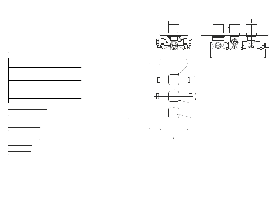
Line Drawing
120
285
Ø15
Ø15
153
108
45
70
231,5
60 - 67 mm
70
Ø15
Item
Quantity
Thermostatic Shower Valve
1
Concealing Plate
1
Thermostatic Shower Valve Control Knob
1
Divertor Control Knob
1
Bath Fill Control Knob
1
Screws
4
Wall Plugs
4
Flow Regulator
2
Hexagonal Allen Key
1
Hot Inlet
Cold Inlet
Outlet 2
Outlet 1
Bath fill
outlet
Divert to Outlet 1 , Outlet 2 or Bath fill
Temperature control
Bath fill on / off