Micro switch, Drive and idler rolls, Drive roll installation/removal – MK Products Prince XL User Manual
Page 12: Idler roll installation and removal
Prince
®
XL/Spool Gun Owner's Manual - Page 5
Micro Switch
The micro switch assembly consists of the micro switch, leads, and
connector. The assembly is secured to the gun block with two (2) screws.
An insulator between the gun block and micro switch prevents accidental
shorting of the switch leads. The leads are laid in the channel under the
motor.
Drive and Idler Rolls
The Prince
XL gun comes standard with a knurled drive roll and a grooved
idler roll, which will handle both steel and aluminum wire with diameters from
.030-1/16 inch. Optional insulated V-groove drive rolls are also available for
aluminum wire if desired (see Optional Kits).
Drive roll tension is accomplished by means of a pressure adjusting allen
screw located on the left hand side of the gun. Proper tension is achieved
when wire does not slip if a small amount of pressure is added to the wire as
it exits the tip.
NOTE:
Over-tightening of the drive rolls will cause excessive
knurling and/or deformation of the wire.
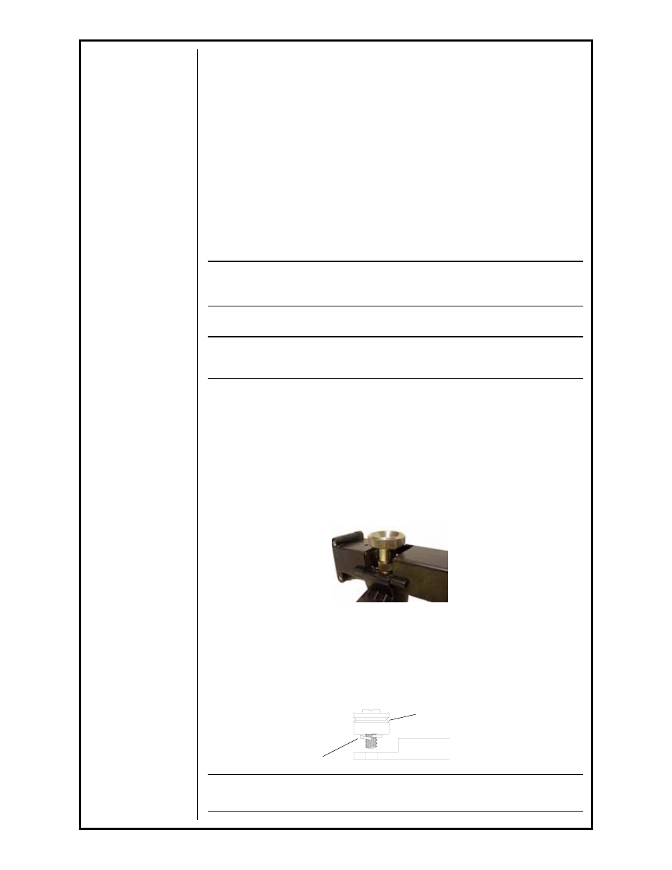
Drive Roll Installation/Removal
NOTE:
Neither of the handles needs to be removed to access the
Drive or Idler Rolls
1. Pull the Cam Lever away from the idler roll. This will relieve the
pressure against the drive roll.
2. Align the Drive Roll Removal Tool (P/N 931-0100) over the flats
of the drive roll. Hold the gun with one hand or on a table
top, with the other hand give the Removal Tool a quick snap-turn
in the CLOCKWISE DIRECTION.
3. Once the drive roll is loose, continue to spin drive roll in the
clockwise direction to remove the drive roll from the gun.
4. Install a new drive roll on the left-hand threaded shaft. The drive
roll will self-tighten when it is feeding wire.
Idler Roll Installation and Removal
1. Using a slot type screwdriver, loosen idler screw, taking care not to
lose lock washer under idler roll.
2. Insert new idler roll and lock washer onto screw, insuring that idler
groove is toward top and lock washer is beneath.
3. Tighten.
NOTE:
Lock washer must be under idler roll or it will not turn freely
Lock Washer
Groove Towards Top
Idler Arm