Installation – Montigo B34DV User Manual
Page 11
Page 11
B-Series DV-2 Gas Fireplace
Part No. XG0160 - 141231
Installation
Example A: (Acceptable Installation)
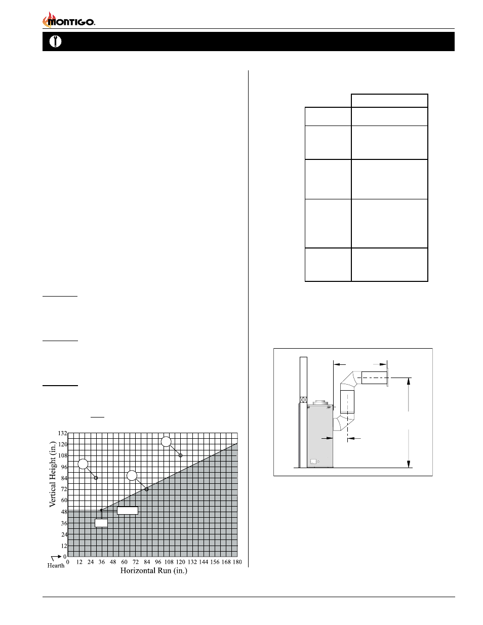
If the vertical dimension from the hearth is 84" and the horizontal
run to the wall flange of the vent termination is 30", this would be
an acceptable installation.
Example B: (Acceptable Installation)
If the vertical dimension from the hearth is 108" and the horizontal
run to the wall flange of the vent termination is 120", this would be
an acceptable installation.
Example C: (Unacceptable Installation)
If the vertical dimension from the floor of the fireplace is 72" and
the horizontal run to the wall flange of the vent termination is 84",
this would NOT be an acceptable installation.
B. Multi-Elbow Installations
For more difficult installation situations, the B-Series DV-2 Rear Vent
may be installed with two - 90° elbows and up to 15' of horizontal run. If
using this installation option, you must adhere to the following guidelines:
Important: Some models are not available to be installed in a rear
vent application. Please refer to the model specifications on page
2 of this manual.
the first 90° elbow must be placed directly on the flue collar
you must have a minimum vertical lift of 50" (measured from the
hearth)
your vent run must fall within the limits set by Figure 20.
Before you install any venting, you must determine whether the venting
run will be acceptable. Unacceptable venting can affect the fireplace's
combustion.
The Venting Graph
Measure the vertical height from the fireplace hearth to the centre of
the termination and the horizontal run from the from the fireplace flue
collar to the wall flange of the termination. Plot on the Venting Graph
(Fig. 20) with an 'X'.
If the 'X' falls on or above the top boundary of the shaded area, the
installation is acceptable.
Figure 20. B-Series DV-2 Multi-Elbow Venting Graph.
NOTES:
All dimension lengths for vertical or horizontal runs are
measured from center of the vent pipe.
Venting runs must fall within the limits set by the venting
graph (see Figure 20).
B
A
32”
C
50”
18"
Max.
15’ Max.
50"
Min.
Figure 21. Multi-elbow installation. (For the B-Series the vertical
distance must be a minimum of 50". The vent run must
comply with the Graph, figure 20).
4" / 7" Venting
A - Termination
MTO-4 (3" Length)
MTO-4F (3" Length)
B - Stucco Kits
MSR (Stucco Frame)
BSR-4 (4" Brick Frame)
BSR-6 (6" Brick Frame)
MOSR (Stucco Can)
C - Flex Sections MFL-1 (12" Section)
MFL-2 (24" Section)
MFL-3 (36" Section)
MFL-4 (48" Section)
D - Rigid
Sections
MEXT-1 (12" m/f Section)
EXT-18 (18" f/f section)
MEXT-2 (24" m/f Section)
MEXT-3 (36" m/f Section)
MEXT-4 (48" m/f Section)
E - Elbows MEL-90MM (m/m 90° Elbow)
MEL-90FF (f/f 90° Elbow)
MEL-90FM (f/m 90° Elbow)
EEL-45 (f/m 45° Elbow)
MFL-6 (72" Section)
MEXT-6 (72" m/f Section)
Installation of Rear Vent DV-2
The following venting components are available from a B-Series DV-2
in a Rear Vent Installation: