Installing the hfk34/ hfk34h cross-flow blower – Montigo HFK-Series Cross-Flow Blower User Manual
Page 2
18
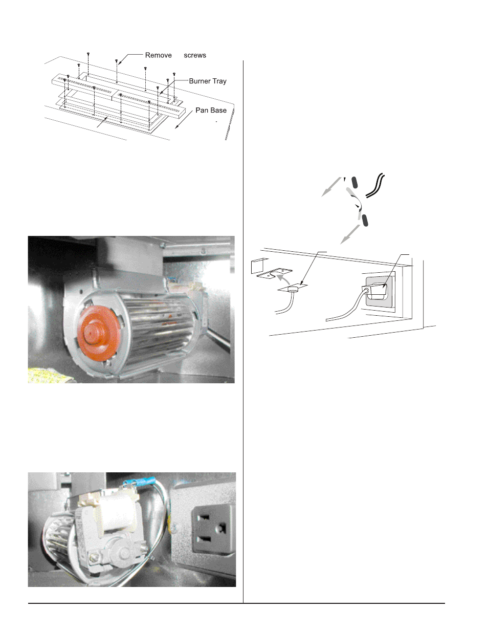
Burner Tray Gasket
XG0625 - 081008
Figure 6. Installing the heat sensor.
Heat sensor
Blower power cord
6. Install the first blower on the left side. Attach the connections on
the fan cord with the connections on the blower. On models H34-
DL, H38-DL, and L42-DL, slide the blowers carefully into place to
the right of the valve. Take care not to damage any pilot tubing or
gas controls. On models L38-DF and L-42-DF, slide the blower into
place carefully through the opening in the base of the firebox.
7. Install the second blower on the right side. Attach the remaining
connections on the fan cord with the connections on the blower.
On models H34-DL, H38-DL, slide the blowers carefully into place
to the right of the valve. Take care not to damage any pilot tubing
or gas controls. On models L38-DF, L42-DF and L-52-DF, slide the
blower into place carefully through the opening in the base of the
firebox.
Figure 4. Positioning the blower on the left side.
Figure 5. Positioning the blower on the right side.
Installing the HFK34/ HFK34H Cross-Flow Blower
Plug the blower's power cord into the receptacle on the PPO
box.
10. Install the heat sensor switch contained in the HFK34H blower
kit:
On models H34DF, H38DF, and H42DF, reinstall the burner
tray as outlined in step 1b and shown in figure 2.
Install the heat sensor switch by sliding it into place under-
neath the burner tray to the right of the gas valve, as shown
below.
11. On models H34DF, H38DF, and H42DF, CAREFULLY reinstall
the log base and logset and ensure that they are properly po-
sitioned as outlined in the fireplace's operation and installation
manual. Once the logset in properly positioned, replace the
glass door. On -L-Series models replace the ceramic panel(s),
decorative beads, and/or decorative rocks.
12. Replace the door as shown in your instruction guide.
13. Turn on the power supply and reconnect the gas supply.
8. On each blower, position the inside of the front top edge with
the mounting brackets on each side of the control compart-
ment, as shown in figures 4 and 5. Fasten both blowers in
place with self tapping screws.
9. If the PPO box has not been factory installed, ensure that the
household electrical supply is shut off at the breaker or fuse,
and connect the two wire leads from the box to the household
electrical supply. Insert the PPO box into the square hole in
the right-hand side of the control compartment and screw into
place.
Figure 3a. Removing the burner tray. (L38DF, L42DF. L52DF Only)
Sensor
Mounting Plate