Warning, Cut out, 24 machine screw moveable bracket – Montigo L-Series Fireplace Surround User Manual
Page 2
XG0905 - 150204.1
Step 6. Placing the Surround
Finally it's time to install the Stainless steel or Black Surround. For
this step it would be helpful to have someone help you hold the sur-
round in place.
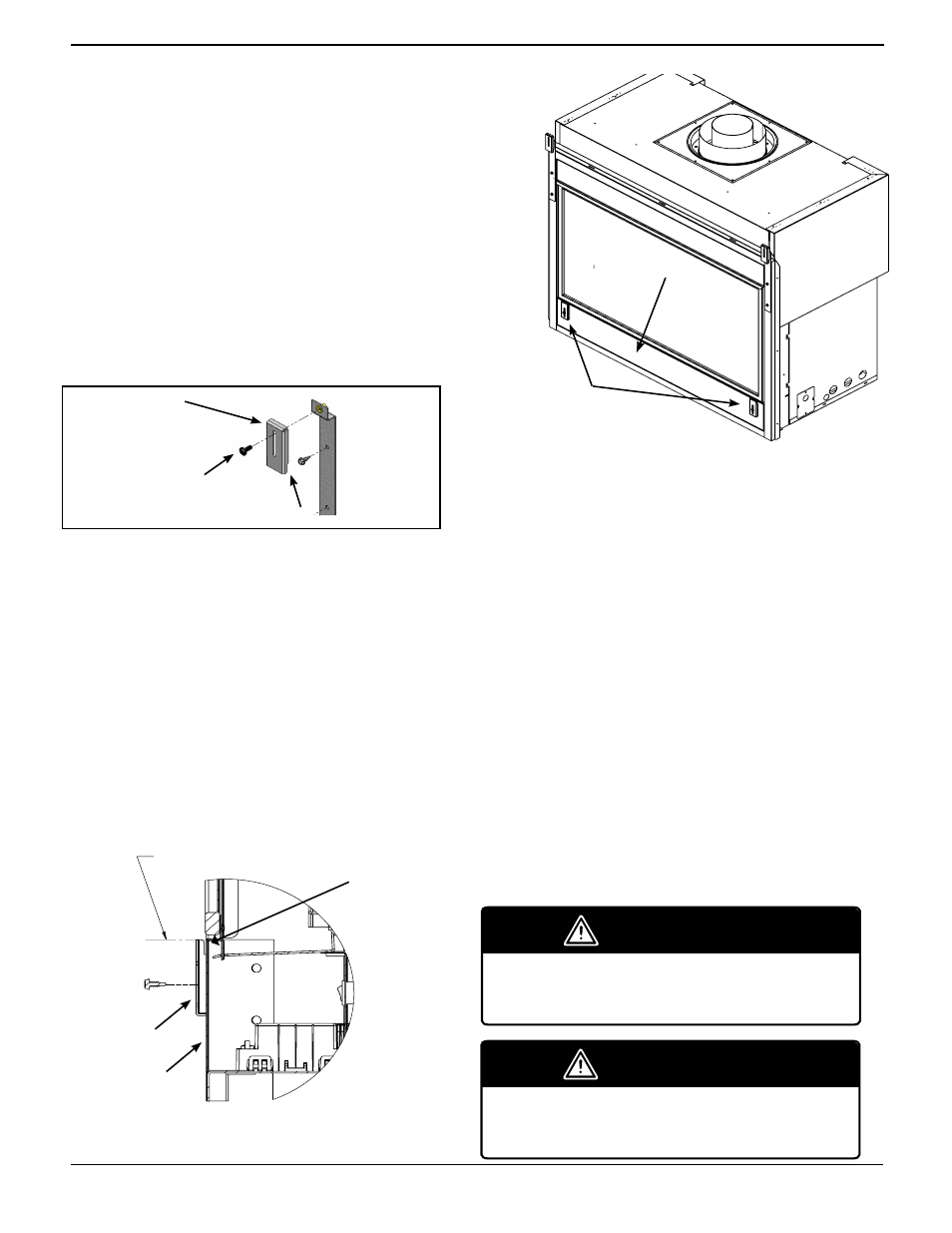
Lift the surround over the four (4) Movable Brackets and slide the
surround downward. The surround should securely lock in place in
the cut out in the lower moveable brackets. Center the surround left
to right.If the surround doesn't clear the top or bottom of the fireplace
you will have to adjust the movable brackets up or down. Remove
the surround place it aside. Adjust the bracket as required. Repeat as
necessary.
Step 7. Final adjusting of the Surround
This step is not necessary if the surround fits tightly around the
fireplace, or the adjustment is acceptable. But, if your surround has
an uneven reveal, or unequal gap around/between the fireplace and
surround, using a carpenters level adjust the Movable brackets as
needed.
Finally place the adjusted Surround back on the Brackets and admire
your Contemporary Montigo fireplace.
Step 3. Install the (2) two Attachment Brackets. (See Figure 2)
Install the two (2) Attachment Brackets you used as a guide. Have
someone hold one of the Brackets in place, using the Hex-tool, place a
self-tapping #8-18 sheet metal hex screw into the hole and twist it into
the hole half way
.
Follow this procedure for the remaining two (2) screws in the first
bracket. After the three (3) screws are in place tighten them in place.
Repeat the procedure in Step 3 for the second Attachment Bracket.
Step 4. Install the (2) two Movable Brackets. (If installed disregard this
step. If not See Figure 3)
Install the two (2) Movable Brackets. (These move up or down to level
and align the surround. This will produce a symmetrical reveal when
correctly adjusted).
Figure 3. Installing the Movable Brackets
Pick up one of the brackets, using the supplied hardware, mount it into
place. Slide the bolt through the bracket 'front to back', (See Figure 3),
then tighten the bolt using a open end wrench or socket.
Follow this procedure for the remaining bolt in the second Movable
Bracket.
Step 5. Installing the Lower Moveable Brackets
Using the self drilling screws supplied secure the moveable brackets to
the front of the fireplaces lower facia. The cut out on the moveable braket
should be such that the cut out is facing up. The moveable bracket
should be level with the top of the fireplace lower facia and spaced
evenly from left to right as to support the weight of the surround. See
figure 4 and 5.
A
A
A
SECTION A-A
FLUSH WITH
VALVE/BOTTOM
PANEL
REVISIONS
REV.
DESCRIPTION
DATE
CHANGED BY
-
.
-
-
1:8
DWG. NO.
SHEET 1 OF 1
WEIGHT:
P38-MAN2
Finish
MATERIAL
DIMENSIONS ARE IN INCHES
TOLERANCES:
FRACTIONAL 1/32"
TWO PLACE DECIMAL .015"
THREE PLACE DECIMAL .005"
ALL BENDS ARE ASSUMED
TO BE 90 UNLESS NOTED
OTHERWISE.
Revision / Date
Drawn by
DATE
NAME
P38
THE INFORMATION CONTAINED IN THIS DRAWING IS THE SOLE PROPERTY OF CANADIAN HEATING PRODUCTS. ANY REPRODUCTION IN PART OR AS A WHOLE WITHOUT THE WRITTEN PERMISSION OF CANADIAN HEATING PRODUCTS IS PROHIBITED.
PROPRIETARY AND CONFIDENTIAL
Y:\CADD\38\P38\P38
March-31-15 12:54:25 PM
SCALE
PC
Description
FACEPLATE MANUAL
A
Revision
03/31/2015
A
A
A
SECTION A-A
FLUSH WITH
VALVE/BOTTOM
PANEL
REVISIONS
REV.
DESCRIPTION
DATE
CHANGED BY
-
.
-
-
1:8
DWG. NO.
SHEET 1 OF 1
WEIGHT:
P38-MAN2
Finish
MATERIAL
DIMENSIONS ARE IN INCHES
TOLERANCES:
FRACTIONAL 1/32"
TWO PLACE DECIMAL .015"
THREE PLACE DECIMAL .005"
ALL BENDS ARE ASSUMED
TO BE 90 UNLESS NOTED
OTHERWISE.
Revision / Date
Drawn by
DATE
NAME
P38
THE INFORMATION CONTAINED IN THIS DRAWING IS THE SOLE PROPERTY OF CANADIAN HEATING PRODUCTS. ANY REPRODUCTION IN PART OR AS A WHOLE WITHOUT THE WRITTEN PERMISSION OF CANADIAN HEATING PRODUCTS IS PROHIBITED.
PROPRIETARY AND CONFIDENTIAL
Y:\CADD\38\P38\P38
March-31-15 12:54:25 PM
SCALE
PC
Description
FACEPLATE MANUAL
A
Revision
03/31/2015
Figure 4. Installing the Movable Brackets on Lower Facia
Figure 5. Installing the Movable Brackets on Lower Facia
Cut Out
Lower Facia
Moveable Bracket
Moveable Bracket
Lower Facia
WARNING
When installing the fireplace - gas lines, fittings,
accessories or any other objects cannot impede the
proper movement of the door buckles.
A
REVISIONS
REV.
DESCRIPTION
DATE
CHANGED BY
-
.
-
-
1:2
DWG. NO.
SHEET 1 OF 1
WEIGHT:
P38-MAN3
Finish
MATERIAL
DIMENSIONS ARE IN INCHES
TOLERANCES:
FRACTIONAL 1/32"
TWO PLACE DECIMAL .015"
THREE PLACE DECIMAL .005"
ALL BENDS ARE ASSUMED
TO BE 90 UNLESS NOTED
OTHERWISE.
Revision / Date
Drawn by
DATE
NAME
P38
THE INFORMATION CONTAINED IN THIS DRAWING IS THE SOLE PROPERTY OF CANADIAN HEATING PRODUCTS. ANY REPRODUCTION IN PART OR AS A WHOLE WITHOUT THE WRITTEN PERMISSION OF CANADIAN HEATING PRODUCTS IS PROHIBITED.
PROPRIETARY AND CONFIDENTIAL
Y:\CADD\38\P38\P38
April-01-15 8:18:44 AM
SCALE
PC
Description
FACEPLATE BRACKET
MANUAL
A
Revision
04/01/2015
10-24 Machine Screw
Moveable Bracket
Cut out
WARNING
Screen Barrier must still be used with the Surround.
The screen should only ever be removed for servic-
ing and then reinstalled before operating fireplace.