Installation – Montigo EDVRSPV47 User Manual
Page 6
f i r e f e a t u r e
EDVRSPV Vertical Power Vent System
Part No. XG1302 - 120110
Installation
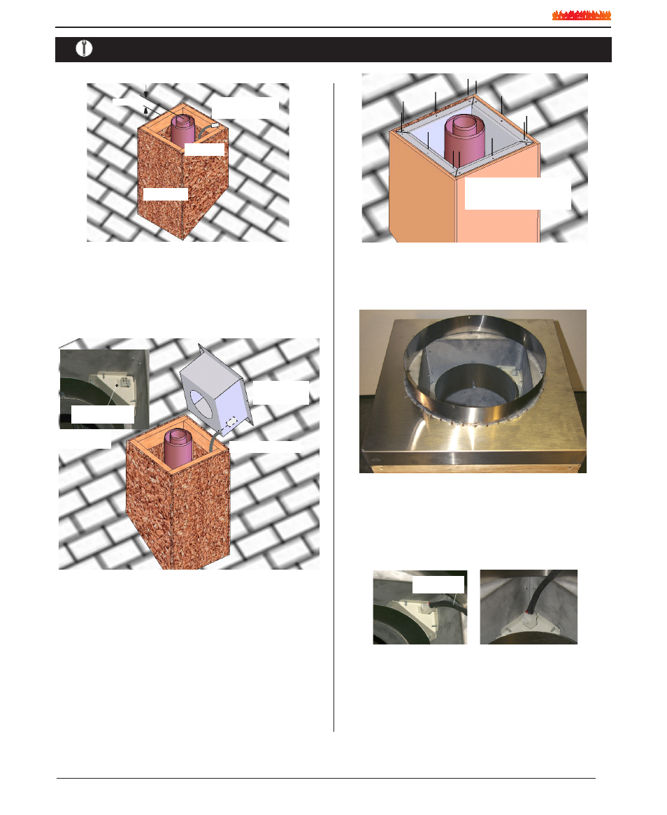
Figure 6. Installation of Rough-in Kit
Step 3.
Install the Power Vent Rough-in Kit. Pull wire harness through
the supplied hole in the bottom corner of the rough-in box, and
snap into the slot provided, (See figure 6 inset).
Electrical Harness
Power Vent
Rough-in Kit
Electrical Harness
Connector Location
Inset
Step 2.
Install the Vent pipe female end up, and 2" to 3" MAX. from the
top of the Constructed Chase. Also, at this point install the Electri-
cal harness, (EPVH-(10-100) that will communicate with the
Power Vent Module.
Vent Pipe
Vent Chase
Electrical Harness
with Connection
2 to 3” MAX
Figure 5.
Figure 7. (Fasten Rough-in Kit to framing)
Step 4.
Install fasteners around perimiter of Rough-in Kit. (Holes supplied
for ease of installation)
Install Fasteners around
perimeter of Rough-in Kit
Figure 8. (Installed Stainless steel cover)
Step 5.
Install the Power Vent, Roof-top Stainless steel cover over the
Installed Rough-in Kit. (You can see the Electrical harness con-
nector in the top right corner).
Figure 9. Figure 9a.
Step 6.
Install the Power Vent Module Power / communication harness.
Hold the Power Vent in close proximity of the assembled Chase,
(with stainless steel cover attached) and plug in the Power Vent
communication / Power Cord. (Note the direction and orientation
of the plug socket). (See Figure 9 & Figure 9a)
Electrical Harness
from Power Vent
Page 6