Motion Sound MS-1771 User Manual
Page 4
4
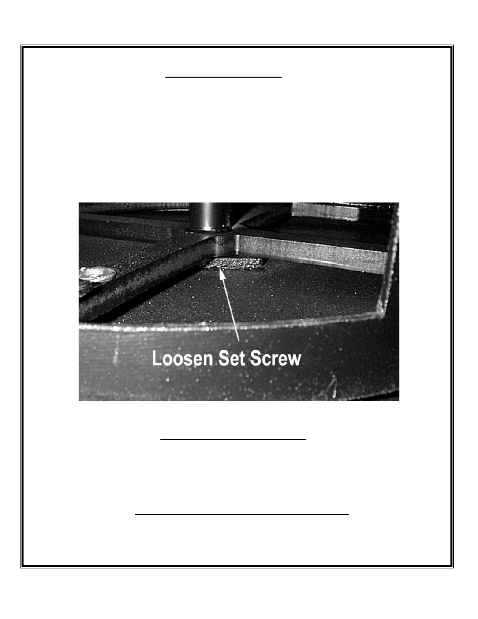
Low Rotor Belt Replacement
1. Remove the center and lower rear cabinet covers.
2. Remove the 15” speaker wires (note polarity) and remove the speaker.
3. Loosen the lower axle shaft set screw (see image).
4. Before the shaft is moved, note a few “O” rings on the shaft between the rotor top and the speaker shelf.
5. Tilt the MS-1771 towards the right to allow the axle shaft to slide down through the hole in the cabinet bottom.
6. Slide the Axle down just far enough to remove the “O” rings and allow a new belt to slip over the rotor top.
7. Use a small screwdriver through the top axle hole to hold the “O” rings in place as the axle is pushed up into the top large
“O” ring bushing.
8. Re-tighten the lower axle support set screw.
Power Supply and remote “turn on”
The MS-1771 supports the 11-pin rotary connector standard including Organ console power on. A standby/off switch on the
rear of the amplifier chassis enables (On) the standby power control relay in the MS-1771. When the organ console is turned
on, a transistor in the Organ console turns on the standby relay powering up the MS-1771. If the standby power switch on the
MS-1771 is off, the amplifier will not power up from the Organ console. Two LED’s indicate system power status by
displaying “standby” and “On” condition. Upper LED = Standby on Lower LED = Power on.
External Volume, Bass and Treble Control PC board.
1.
Note ribbon cable polarity and then remove. The connector may be held in place by a small amount of silicone rubber.
2.
Remove the mounting screws.
3.
The tone control board contains the Bass, Treble and Volume external controls.