MultiDyne HD3000 Gen2 Series User Manual
Page 6
Instruction Manual, HD3000 Series
3
REV C, Feb 24, 2015
POWER REQUIREMENTS
The HD3000 Series operates from 115 or 230 VAC with a wall-mount power supply or 9 to 24
VDC @ >= 1A using a coaxial type connector (sleeve ground) on the rear panel labeled
POWER 9~24VDC. If desired, the units could be powered from a 12V battery.
INSTALLATION
The installation and start up of the HD3000 Series do not have special requirements. No
special sequence must be followed to connect and start up the units. RG59 or other 75 Ohm
Coax cable must be used for the BNC inputs and outputs and single mode fiber with the
selected proper connectors must be used for the fiber link. Optionally, multimode fiber can be
used with a shift patch on the transmitter, or if the units are ordered with MM optics, though
significantly reduced range performance is expected for this scenario. The HD3000 Series
come standard as stand-alone units. An optional rack-mounting kit is available to mount up to
6 units in a 1 Rack-unit or 1 ¾” by 19” rack space. The part number is –RM6.
SETTINGS FOR NON-SDI SIGNALS
The HD3000 series comes configured to satisfy the needs of most users.
This includes automatic reclocking and auto mute for SMPTE 3G, HD and SD signals and
support for DVB/ASI.
The factory setting is to auto mute the link when there is not a valid SMPTE signal present,
and to attempt to reclock any signals that are close to the standard SMPTE rates of 270,
1485 or 2970 MBPS. However, it is possible to pass other non SMPTE rates and digital
signals by setting dip switches located inside the units to the non-default values.
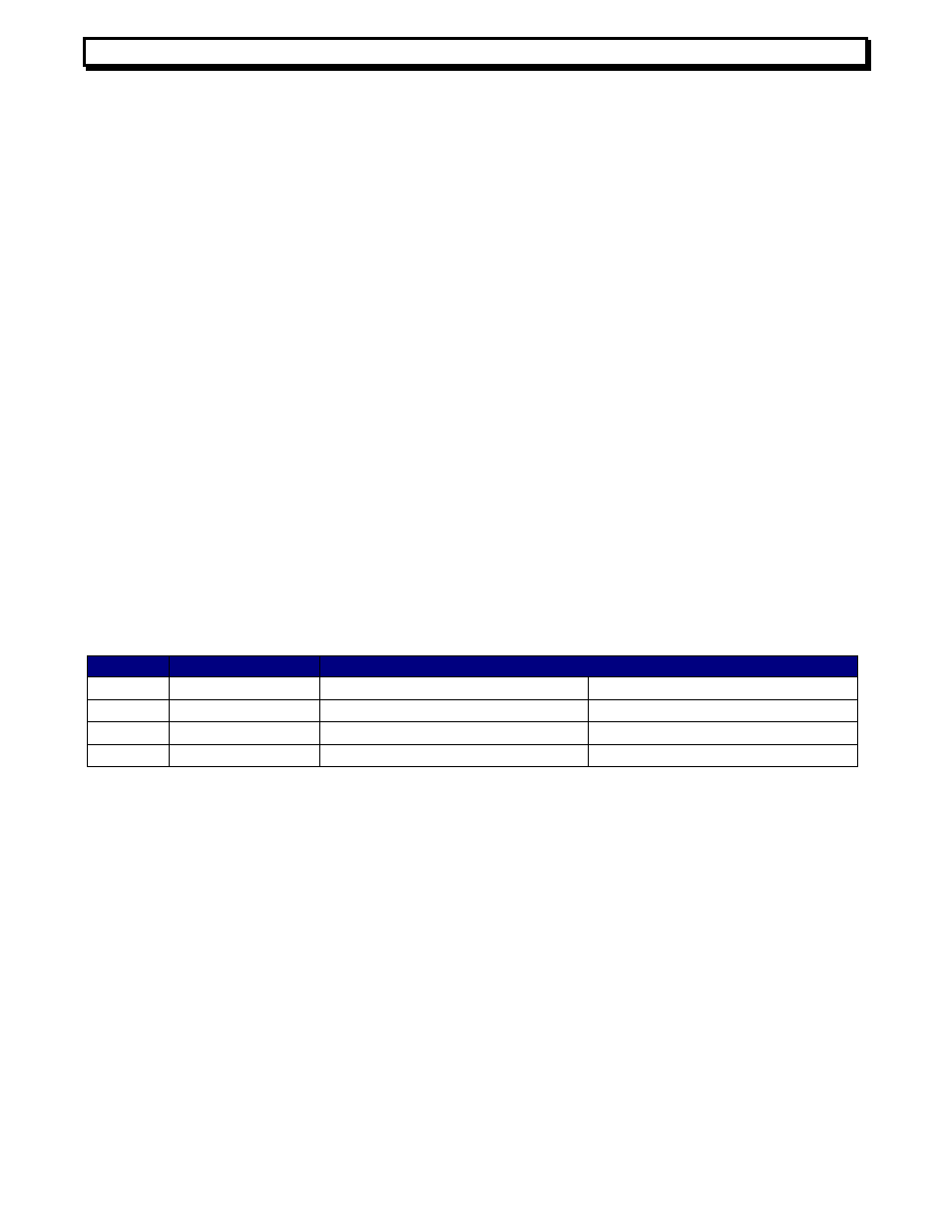
These settings are controlled by SW1. The settings are as follows:
In the -1TX, use settings for Ch 1. The Ch 2 settings are ignored. In the -1RX or -DR, use
settings for Ch 2. The Ch 1 settings are ignored. In the -TRX, Ch 1 refers to the TX section
and Ch 2 to the RX section. To access the switches, remove the 2 screws on the rear panel.
Slide the pcb out.
MAINTENANCE
There are no user serviceable parts or internal adjustments other than the switch
selections described above. As always, it is recommended that all optical fiber
connections be checked periodically for cleanliness and integrity. For repair and service,
please call the factory.
Sw 1
Function
Setting (Default values in Bold)
1
Reclock Ch 1
Off = reclock
On = bypass
2
Reclock Ch 2
Off = reclock
On = bypass
3
Automute Ch 1
Off = never mute
On = automute
4
Automute Ch 2
Off = never mute
On = automute