Nortec NH Series User Manual
Page 43
Start Up | 40
f. Drain Cycle
1. The following indications are provided for the set-flushing interval
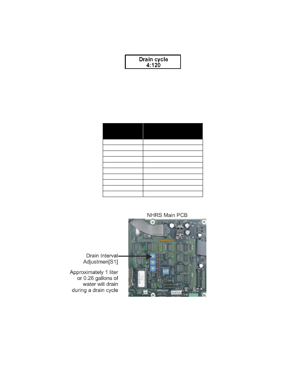
Left: Switch setting on rotary switch “S1” (4 in example)
Right: Set flushing interval (120 in example)
The flushing interval is set on switch “S1” on the control board.
Table 11: Drain Cycle intervals with rotary switch "S1"
S1 Position
Drain Intervals at
100% Steam Capacity
0
0 min
1
720
2
360
3
180
4
120
5
60
6
30
7
20
8
10
9
5
NOTE: S1 rotary switch is set at factory to “9”.
Figure 31: Drain Cycle adjustment S1
NOTE: Water quality conditions resulting in component failures are not covered
under Nortec’s standard warranty. The factory settings are based on the
following water conditions when the unit leaves the factory.
Should you have water conditions more aggressive that the stated parameters,
consult the factory for a new drain cycle setting to help improve your scale
management.