2 cautions, 3 cabling and wiring – Northern Airborne Technology AA36-100 User Manual
Page 14
AA36-100 Digital ICS Tie Line Adapter Manual
SM58 Rev. 4.00
2.3.2 Cautions
⇒
In all installations, use shielded cable exactly as shown and ground as indicated.
Significant ground loop and noise problems may result from not following these
guidelines. Ensure chassis is grounded to provide proper shield terminations.
⇒
Use caution when routing microphone wiring, as it carries low-level signals prone
to coupling from other sources.
⇒
Do not take a ground from the instrument panel or similar location that shares a
ground return with a turn and bank, horizon or other motor driven instrument.
This may cause the unit to pick up the sound of the motor as ground loop
interference.
2.3.3
Cabling and Wiring
All unshielded wire should be Tefzel MIL-M-22759 or equivalent. For shielded wire
applications, use Tefzel MIL-C-27500 shielded wire with solder sleeves (for shield
terminations) to make the most compact and easily terminated interconnect. Follow the
wiring diagrams in Section 2.6 as required.
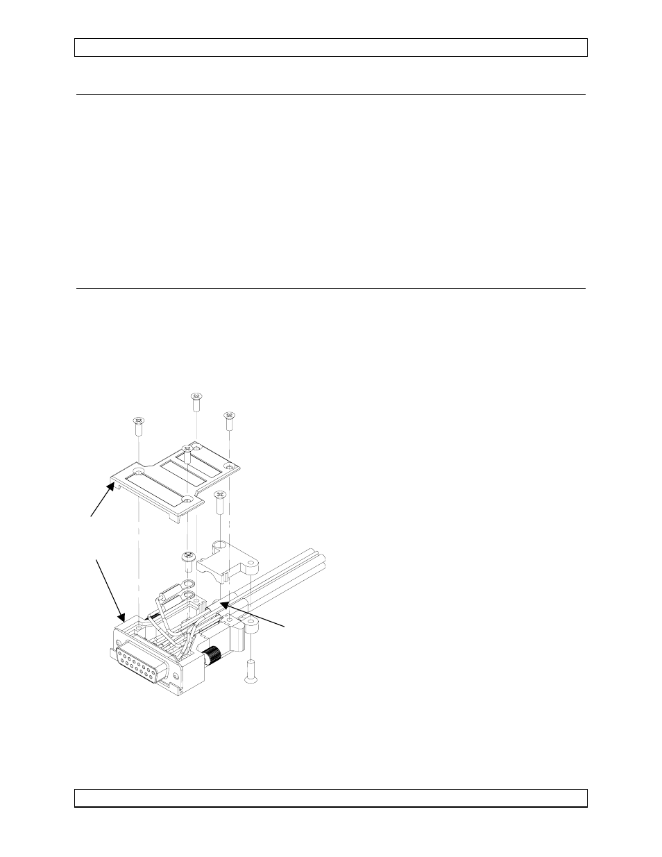
Solder
Sleeves
Metal
Hood
Utilizing solder sleeves, create up to 3
shield pigtails in the wiring harness, as
shown in the Interconnect Diagram
(AA36\100\403-0, Rev 1.00 or higher).
Each pigtail should be no more than
3.0” long.
Note: The hood is a ‘two-piece’ unit,
and is assembled after the wiring
is complete.
All wiring should be at least 24 AWG,
except power and ground lines, which
should be at least 20 AWG. Ensure
that all ground connections are clean
and well secured.
To prevent system failure or inadequate equipment protection, supply power from a
dedicated 1.0 A circuit breaker.
Page 2-2
Nov 14, 2003
ENG-FORM: 805-0104.DOT
PROPRIETARY AND CONFIDENTIAL TO NORTHERN AIRBORNE TECHNOLOGY LTD.