Olson Technology OTPN-3850-SA User Manual
Page 6
025-000641 REV X5
Page 6
Olson Technology, Inc.
OPTICAL CONNECTORS AND CLEANING
The standard optical connectors on the OTPN-3850 are
SC/APC angle-
polished connectors. The internal fiber ends can be damaged by the insertion of con-
taminated connectors. Some types of customer damage to the connectors are not
covered under the warranty. Fiber connectors should never be left uncovered.
Prepackaged alcohol wipes are the most convenient means of cleaning optical connec-
tors. Clean alcohol and lint free wipes or swabs may also be used.
INTERNAL CONTROLS
There are no internal user adjustments. There is no reason to open the unit. Any
attempt to do so will void the manufacturer’s warranty.
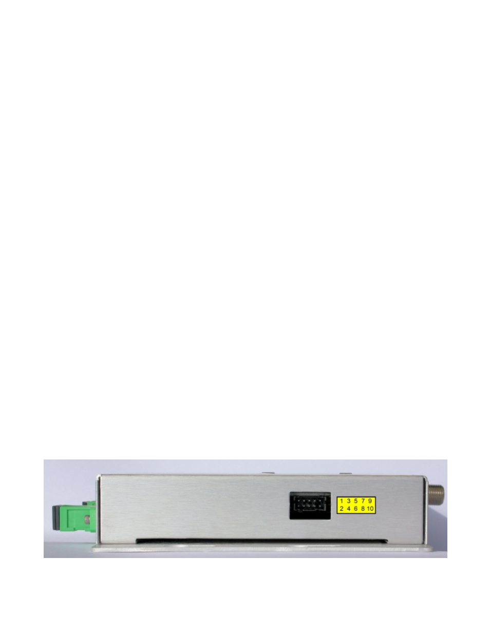
EXTERNAL INDICATORS AND CONNECTORS
There are two external indicator lights and a 10-pin electrical connector. One of the indicators
lights green to indicate that power has been applied to the unit. The second red indicator only
lights red when the 1550nm optical input power drops below -10dBm.
The 10-pin connector mates to the following connector;
OTPN-3850 Connector: Molex Part Number: 87833-1020
Mating Connector: Molex Part Number: 51110-1051
Terminals: Molex Part Number: 50394-8100
The function of the ten (10) pins is shown below;
Pin 1 Alarm Collector (Optically isolated NPN transistor) (Yellow on OTPS-12A-10M)
Pin 2 Alarm Emitter (Optically isolated NPN transistor) (Blue on OTPS-12A-10M)
Pin 3 Input Power, +12 to +16 Volts DC (Red on OTPS-12A-10M)
Pin 4 Ground (Black on OTPS-12A-10M)
Pin 5 Optical Monitor (Through 1K resistor. See Figure 3.) (White on OTPS-12A-10M)
Pin 6 +5 Volts (Through 200 Ohm resistor) (Orange on OTPS-12A-10M)
Pin 7 (No wire on OTPS-12A-10M)
Pin 8 Ground (Black on OTPS-12A-10M)
Pin 9 (No wire on OTPS-12A-10M)
Pin 10 (No wire on OTPS-12A-10M)
Olson OTPS-12A-10M (Sold separately) is recommended for use with the OTPN-3850.
GREEN
FIGURE 2 - Electrical Connector Pin Configuration