Olson Technology OTPN-3850-SA User Manual
Page 7
025-000641 REV X5
Page 7
Olson Technology, Inc.
SETUP and OPERATION
Setting up the two transmitters shown in Figure 4 is key to successful operation. We recom-
mend the following steps. 1) Adjust the RF drive level into the CATV transmitter to yield 3%
OMI per channel. Measure it’s optical output power. 2) The optical output of the L-Band trans-
mitter should be set about 5dB below the optical output power of the CATV transmitter. This
may require an optical attenuator.
Mount the OTPN-3850 and apply power. Connect the incoming fiber (
1550nm CATV signal from the headend to the residence) to the
port. Connect the
upstream fiber (the fiber that carries the 1310nm & 1490nm Ethernet signals from the resi-
dence to the headend) to the Optical Out port. Connect the Wideband Output “F” connector to
the equipment that processes the CATV and L-Band signals. Often this may be an L-Band
DeStacker. The OTPN-3850 is designed for optimum performance at an optical input of -4dBm
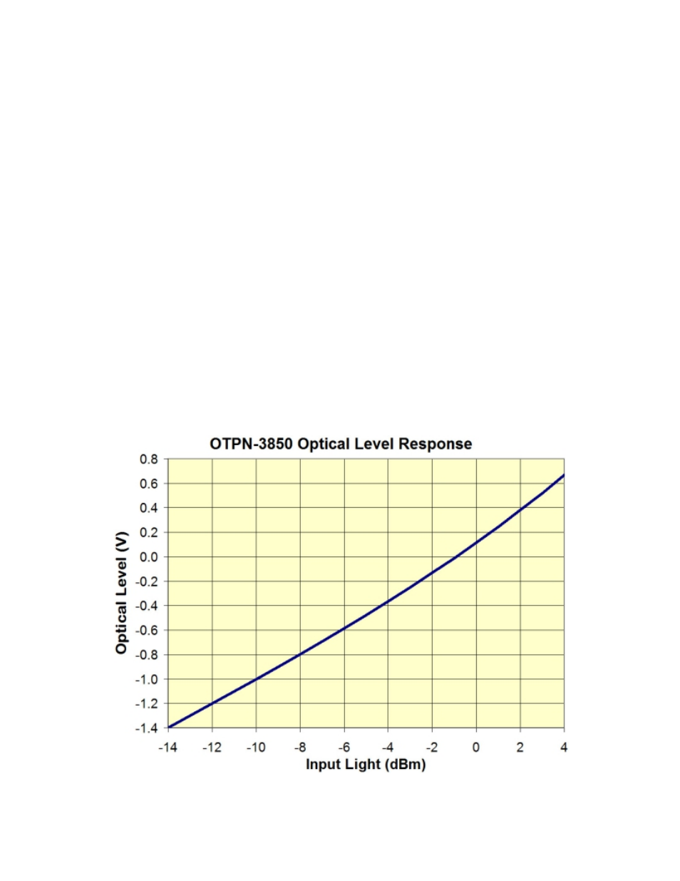
(1550nm power only). The easiest way to verify the 1550nm input power is to measure the
voltage on pin 5 of the electrical connector (See Figure 2 to locate pin 5). The voltage that is
measured on pin 5 can be interpreted in Figure 3. An optical input of -4dBm will yield a voltage
of about -0.365 Volts on pin 5. The OTPN-3850 will give acceptable CATV performance for a
1550nm optical input ranging from 0dBm to -6dBm. This corresponds to voltages on pin 5
from +0.115 Volts (0dBm) to -0.585 Volts (-6dBm). This is the preferred method to verify the
1550nm power. An optical power meter can be fooled if there is 1490nm or 1310nm energy on
the fiber as well. The Optical Alarm LED should be dark and the Power LED should be lit green.
The system should now be functional.
Now verify the CATV RF Levels. They should be about +23dBmV per analog CATV channel.
Now return to the L-Band transmitter and adjust the RF drive level so that the L-Band channels
are about +13dBmV or less.
the fiber that carries the
Optical In
FIGURE 3 - Optical Monitor Output Voltage vs. Input Light Level