ONICON System-30 BTU User Manual
Page 17
Advertising
11451 Belcher Road South, Largo, FL 33773 • USA • Tel +1 (727) 447-6140 • Fax (727) 442-5699 • [email protected]
System-30 BTU Measurement System Manual 05/14 - 0667-2 / 18335
Page 17
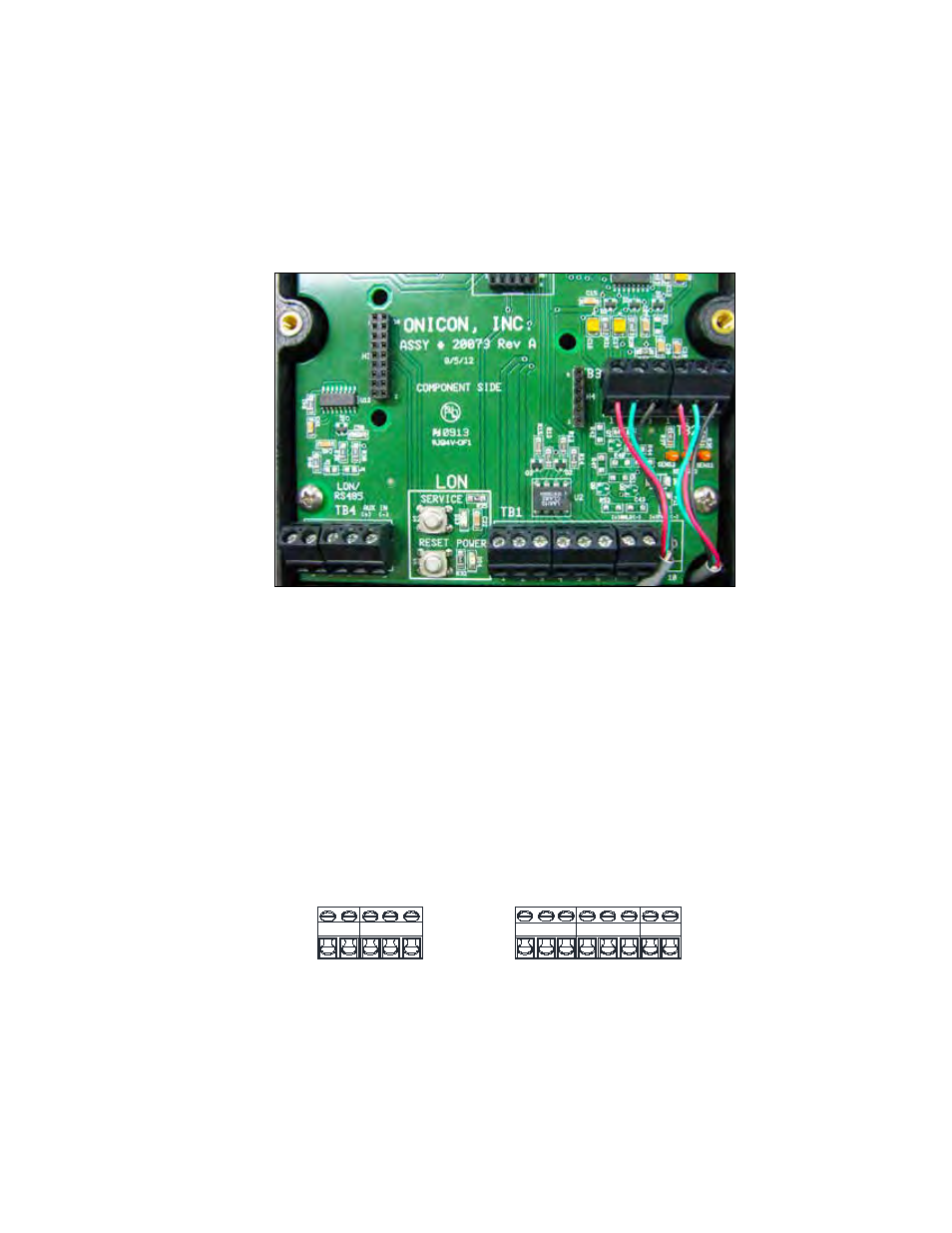
3.3.2 Electrical Wiring
Connect all BTU meter signal outputs to terminal strip T1 and/or T4 (optional
communication output) as shown below.
Then connect the 24 V AC/DC input power to terminal strip T1. The standard SYSTEM-30
is configured for 24 V AC 60 Hz operation or 24 V DC operation. Do not connect the 24 V
AC/DC source until all other signal connections have been made and verified.
View of Signal Connection Board
1 2 3 4 5
1 2 3 4 5 6 7 8
TB1
TB4
+ -
B
tu Mode
1C
on
tact
B
tu Mode
2 C
ontact
}
}
}2
4V AC/DC
+ -
}Analo
g O
utput
+ -
}RS485
+ -
}Aux Pul
se Input
RS4
85
Comm
on
Advertising