Installation template installation instructions – OpenEye CM-206 User Manual
Page 2
Installation
Template
Installation Instructions
Precautions
• Do not attempt to dismantle the camera module mounted within the dome. There
are no user serviceable parts in the camera module. Refer servicing to a qualifi ed
professional.
• Handle the camera with care. Do not abuse the camera. Avoid striking or shaking
it. Improper handling and storage could damage the camera.
• Do not operate the camera beyond its temperature or power source rating. Refer to
the environmental information provided in this document.
Emissions
• FCC COMPLIANCE: This equipment complies with Part 15 of the FCC rules for
intentional radiators and Class B digital devices when installed and used in ac-
cordance with the instruction manual. Following these rules provides reasonable
protection against harmful interference from equipment operated in a commercial
area. This equipment should not be installed in a residential area as it can radiate
radio frequency energy that could interfere with radio communications, a situation
the user would have to fi x at their own expense.
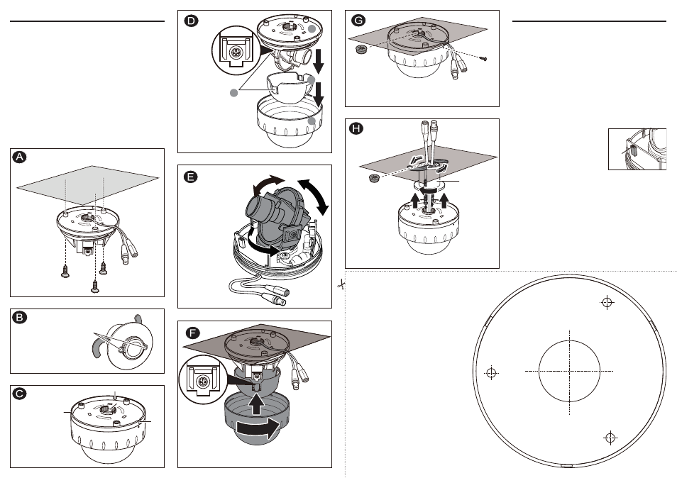
Surface mount (in wall or ceiling)
Using Quick Install Adapter
• Cut a 1.3” (35mm) hole in the mounting surface as indicated
on the template (T5).
Using Screws
• Drill three 1/4” (7.5mm) holes as indicated on the template
(D5) and insert a wall anchor in each hole. Use the supplied
D5 screws to attach the camera.
Cable Access
• The cables are threaded through the base knockout (shown in
C1). It is threaded for use with the quick install adapter.
• When mounting the dome on a surface using the three D5
screws, use one of the side knockouts as indicated by C3 for
cable entry. See the Installation Instructions for instructions on
opening the required knock-out panel.
1. Remove the dome cover and the camera liner
Gently turn the dome cover counter-clockwise to unlock and pull free of the dome
base. Remove the camera liner by gently pulling it free of the two notches (D4) in
the camera base (see fi g. D).
2. Use the template to mark-out and prepare the mounting area
When mounting the dome to a ceiling or wall using screws, fi rst knock out the
screw access holes (C2) that correspond to the template marks “D5”. This can be
done by using a cross-point screwdriver. When mounting the dome to a ceiling
using the quick install adapter, use the template to cut a hole as the circle marked
“T5” with a hole cutter.
3. Open the required knock-out panel
Use a sharp knife or side cutter pliers to cut one of the side knock-outs (C3) to the
size required to allow cable entry. Be careful not to hurt yourself or damage the
camera when using knives and side cutter pliers.
4. Mount the dome enclosure
Using one of the mounting schemes discussed on this sheet (either using screws
or the quick mount adapter), fi x the dome enclosure in place.
5. Connect the wiring
Feed the pre-connected main lead (that feeds
to the connections G1 and G2) through the ap-
propriate point and connect it to your video out
and power in cables.The service monitor jack is
provided for temporary video connection when
focusing the camera.
6. Adjust the camera position
You can adjust the focusing position by rotating
and panning the camera base (see fi g. E).
7. Install the camera liner
Carefully fi t the camera liner (F1) over the camera base so that it snaps into place
as shown in fi g. F and does not obstruct the camera lens.
8. Complete installation
Insert the 3/4” cable entry sealing plug (G3) in the dome base, then push the
cables (G1 and G2) through the dome base and the 3/4” cable entry sealing plug
(G3). Make sure the plug is properly installed in the camera base. Replace the
dome cover (F2) and rotate to close it as shown in fi g. F. Use the supplied T6
screw to secure the cover and prevent tampering (see fi g. G).
9. Complete installation (quick install adapter)
Insert the 1/2” cable entry sealing plug (H3) in the quick install adapter (H1) and
insert the adapter the hole cut using the provided template as a guide. Use the
screws on the adapter to adjust the position of the two locking arms (B1) on the
quick install adapter and adjust to the mounting surface. Push the cables through
the opening (H1) and 1/2” cable entry sealing plug (H2). Make sure the plug is
properly installed in the camera base. Thread the dome onto the quick install
adapter. This takes about 1 1/2 turns. DO NOT OVERTIGHTEN.
B1
B1
C1: Threaded base
C2: Screw access holes
C3: Cable knock-outs
F1: Camera liner
F2: Dome cover
D1: Dome base
D2: Camera liner
D3: Dome cover
D4: Notches (on both sides)
G1: Video output connector
G2: Power input connector
G3: Cable entry sealing plug (¾”)
H1: Quick install adapter
H2: Cable entry sealing plug (½”)
Rotate and pan the camera
base to the desired position.
DO NOT rotate/tilt the disk
beyond its maximum allowed
range (350/80 degrees) or
damage may occur.
Make sure the wires are
arranged in a direction that
allows you to rotate/pan the
disk smoothly.
Push the camera
liner up to the
base until it clicks
into place.
Loosen screws, but not remove
them,to fi rst extend the locking
arms. Then tighten the screws
suffi ciently to compress the arms
to adjust to the mounting surface;
however, DO NOT OVERTIGHTEN.
Mount with screws
Use Quick Mount Adapter
C3
C3
C3
C2
C1
C2
C2
D1
D2
D3
D4
T6 screw
G2
G1
G3
H1
H2
Service monitor
jack
D5
D5
D5
T5