Installation, Jusing the quick install adaptor, Mount using screws – OpenEye CM-170 User Manual
Page 2: Template, Mount on a us single gang box: k, Flush mount using locking arms
Locking Arms
J
Using the Quick Install Adaptor
1. Remove the dome cover and the camera module
2. Open the required cable entry
4. Connect the wiring
3. Mount the camera base
12VDC
GND
Video Output
Power Input
Wire-ended adaptor lead
E
E1
Red: +12VDC
Black: 0VDC
A
B
Mount Using Screws
5. Replace the Camera Module
F
6. Adjust the camera position
7. Install the camera liner
8. Replace the Dome Cover
G
The dome cover
The dome base
index mark
index mark
C1
C2
C3
C4
C6
C5
C
small knock-out
large
knock-out
rubber grommet
sealing plug
side
cable entry
base
cable entry
K
Mounting Surface
Video-Power Cables
1/2”Rubber
Grommet
Mounting Surface
Cable Entry
3/4”
Rubber Grommet
D
T1
T1
T1
T1
Template
Installation
Use the supplied large torx driver to loosen the four cover
screws. The screws are captive and will remain in the
cover (image A).
Loosen the gimbal securing screws to remove the camera
module (image B).
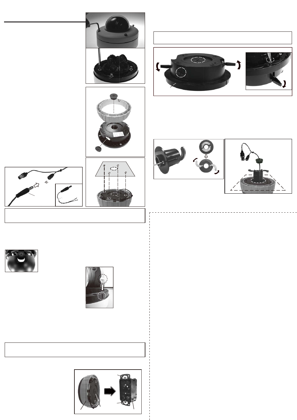
Cut a 5.5” (140mm) hole in the mounting surface as indicated by the template marking T3. Insert the dome
base and turn the silver-colored screws counter-clockwise by 180° to extend the locking arms and tighten
them against the mounting surface (image I).
Cut a 1.5” (38mm) hole in the mounting surface using the T2 marking on the template. Insert the adapter
and turn the screws counter-clockwise one turn to extend the arms, then turn the screws clockwise to pull
the arms toward the flange and secure the adapter to the mounting surface (image J).
Push the cables through the opening and the 1/2” rubber grommet. Make sure the grommet is properly
installed on the adapter to prevent dust penetration (image K).
Note: To protect against dust and moisture penetration, always use the large rubber gasket on the dome
base when installing.
IMPORTANT: If the dome is mounted externally using screws, use the suppled rubber o-rings over each of
the four mounting holes of the dome base to ensure a moisture resistant seal. Tighten the screws sufficiently
to compress the o-ring moisture seals located underneath the screwheads. Do not overtighten.
IMPORTANT: If the dome is mounted externally, use a suitable sealant aroung the cable entry hole to
ensure a moisture resistant seal. This prevents water vapour, from the connected conduit, from condensing
inside the housing.
Tighten the gimbal screws with a screw driver to re-install the camera module.
Adjust the camera position by rotating and panning the camera base. The focus and range of the lens
can also be adjusted
Carefully fit the camera liner over the camera base so that it snaps into place
(image F). Do not obstruct the camera lens.
Replace the dome cover using the index mars (image G)
to align it. Tighten the torx screws to secure the cover. Do
not overtighten.
Feed the pre-connected main lead through one of the
cable access points and connect it to your video output and
power input cables. A wire-ended adaptor lead (E1) is
suppled for use with power supply cables that are not
terminated with the appropriate power connector.
For 12VDC operation: Connect the red lead to positive and
the black lead to negative.
Use either the base cable entry (C1) for the side cable
entry (C2) as required. When surface mounting and using
the side cable entry (C2), open the large (C3) or small (C4)
knock-out on the outer ring to required size by cutting
away excess material. Rotate the outer ring so that the
knock-out aligns with the side cable entry. Seal an unused
side cable entry with a sealing plug (C5). Use the supplied
rubber grommet (C6) to prevent dust penetration when
using the base cable entry. For external applications,
conduit should be used to carry cables into the housing.
Mount the camera base, using screws, on a US single
gang box, using the flush mount locking arms, or using the
quick install adaptor. See the individual instructions below
and at right.
When mounting the dome to a ceiling or wall using screws, knock out the four screw access holes on the
base that correspond to the template marks T1 using a phillips head screw driver (image D). Drill four
holes in the mounting surface using template marks T1 and cut a hole using template marking T4 for the
3/4” base cable entry.
When flush mounting or surface mounting using the outer ring, ensure that the large rubber gasket
(image I) is in place under the lip of the dome enclosure.
When mounting the dome to a single gang box,
carefully remove the screws from the securing
position on the box. Insert the 3/4” rubber
grommet in the base cable entry to prevent dust
penetration and push the cables through the dome
base and grommet.
Mount the dome base using the two screws
removed earlier. Tighten the screws sufficiently to
secure the base to the box (position T5, image H).
Mount on a US Single Gang Box:
K
US Single Gang Box
Securing
Position
(T5)
Securing
Position
(T5)
H
S
T5
T5
Dome Base
3/4”
Rubber Grommet
Flush Mount Using Locking Arms
Locking Arm
Locking Arm
3/4”Base Cable Entry
1/2” Side Cable Entry
Locking Screw
Extending the Locking arms with screw driver.
Rubber Gasket
Locking Arm
I