Pennco NATURAL GAS TO LP User Manual
Page 3
3
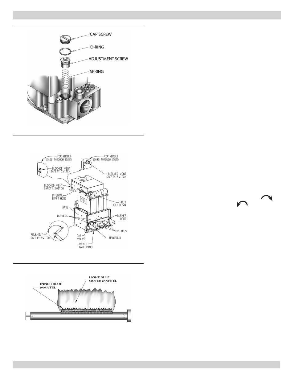
Figure 4 - Gas Valve
NATURAL GAS TO LP CONVERSION INSTRUCTIONS
• Thermostat actuates on call for heat, completing circuit
to control.
• Completed circuit to control activates circulator. Damper
will close end switch inside the damper. This will
complete circuit to ignition system and ignition takes
place.
• Power is interrupted between control system and
ignition system if boiler water temperature exceeds high
limit setting on boiler mounted high limit control. Power
remains off until boiler water temperature drops below
high limit setting. Circulator continues to operate under
this condition until thermostat is satisfied.
• Blocked flow of combustion products through boiler
venting system causes blocked vent safety switch to
shut main burner gas off. If boiler flueway becomes
blocked, flame rollout safety switch will shut main
burner gas off. See Figure 5. If either condition occurs,
do not attempt to place boiler back into operation.
Contact qualified service agency.
• Main burner flame should have well defined inner blue
mantel with lighter blue outer mantel. See Figure 6.
• Pilot flame should envelop ⅜ to ½ inch of tip of the pilot
thermocouple, ignition/sensing electrode or mercury
sensor. See Figure 7.
Checking Gas Input Rate To Boiler
• Adjust gas input to boiler by removing protective cap on
pressure regulator and turning screw clockwise
to
increase input and counterclockwise
to decrease
input.
• Set LP gas manifold pressure at approximately 11.0
inches water column. Manifold pressure is taken at
outlet side of gas valve.
• Check for CO2 and CO levels to assure proper operation.
• Change burner orifi ces if fi nal manifold pressure varies
more than plus or minus 0.3 inches water column from
specified pressure.
• Primary air adjustment is not necessary, therefore air
shutters are not furnished as standard equipment. Air
shutters are available on request where required by
local codes or conditions.
Figure 6 - Burner with Mantel
Figure 5 - Burners, Gas Valve, & Manifold