Switch position – Protech Audio 51003 User Manual
Page 4
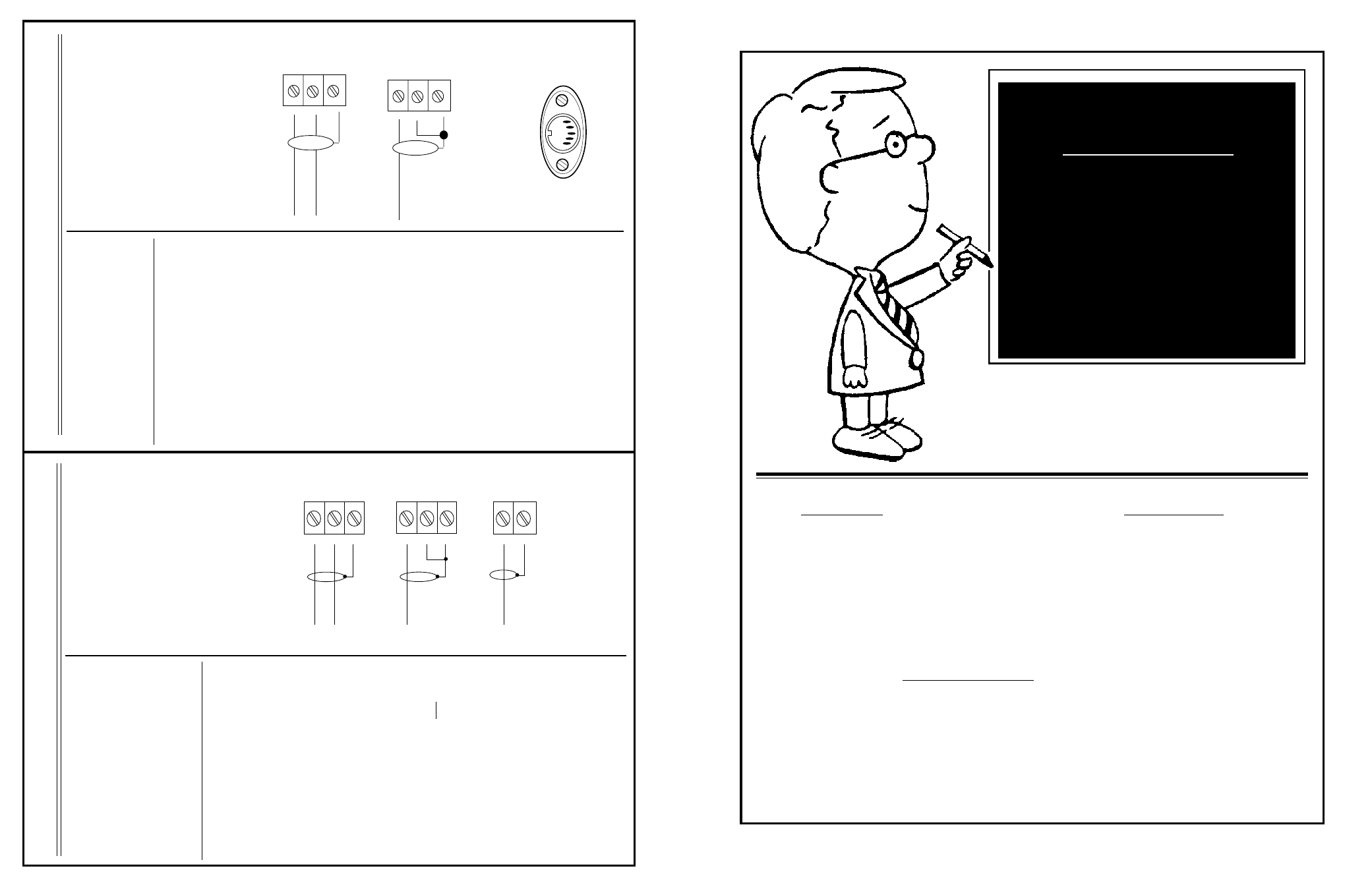
INPUT SECTION
OUTPUT SECTION
The
Model
51003
Audio
Mixing
System
is
designed
to
mount
in
a
standard
19"
wide
EIA
rack.
Each
unit
requires
1.75"
of
ver-
tical
rack
space.
Care
should
be
taken
not
to
mount
the
unit
next
to
power
supplies,
power
amplifiers, or other equipment which gen-
erate
strong
AC
fields.
The
steps
for
install-
ing
the
unit
are
as
follows;
After
input
and
output
section
have
been
configured,
proceed
with
installation
of
unit
in
rack.
Slide
PC
assembly
back
into
chassis
until
fully
seated
in
mating
connectors
(front
panel
should
be
flush
with
mounting
brackets).
Mount
unit
in
rack,
using
four
machine
screws
of
sufficient
tensile
strength
to
sup-
port
unit
properly.
Terminate
all
audio
inputs and outputs, using double conduc-
tor
shielded
cable,
as
shown
below
and
in
output
section.
This
concludes
the
configuration
options
for
the
input
section.
R
efer
to
the
output
section
on
this
page,
for
output
configuration
options.
With
unit
firmly
on
workbench,
loosen
two
thumbscrews
located
on
each
end
of
front
panel,
and
slide
PC
assembly
out
of
chassis.
Check
that
ground
lift
switch
(#1)
is
in
the
on
position.
Slide
Mic/Line
selector
switches
(#2)
to
the
desired
positions.
Slide
DIP
switch
(#3)
position
A
to
on
position
for
each
input
needing
Phantom
Power.
Slide
DIP
switch
(#3)
position
D
to
off
position
for
each
input
not
needing
LOW-CUT
filter.
If
required,
slide
DIP
switch
(#3)
posi-
tions
to
off
position
for
reduced
gain
on
each
channel
(see
chart
on
page
5).
If
required,
slide
priority
switch
(#4)
to
IN
p
osition
to
activate
automatic
priority
feature.
1-
2-
3-
4-
5-
6-
7-
INPUT SECTION CONFIGURATION
This
concludes
the
connections
for
the
input
section.
Refer
to
the
output
section
on
this
page,
for
output
connection
informa-
tion.
UNBALANCED INPUT CONNECTION
BALANCED INPUT CONNECTION
AUXILLARY INPUT CONNECTION
SH
HI
HI
LO
SH
HI
LO
SH
The
following
configuration
and
installation
steps
should
be
done
only
after
the
input
section
has
b
een
c
onfigured.
T
he
steps
a
re
as
follows;
OUTPUT SECTION CONFIGURATION
1 -
2 -
3 -
4 -
5 -
6 -
With
unit
firmly
on
workbench,
loosen
the
two
thumbscrews
on
each
end
of
front panel, and slide PC assembly out
of
chassis.
If
necessary,
slide
the
LOC/RMT
switch
(#5)
to
RMT
position
to
allow
remote
control
of
the
Channel
B
output
level.
If
necessary,
slide
the
EQ
switch
(#6)
to
the
OUT
position
to
bypass
the
tone
control
section.
If
necessary,
slide
the
LIM
switch
(#7)
to the OUT position to bypass the lim-
iter
section.
Turn
OUTPUT
control
knobs
(#8)
fully
counterclockwise.
Check
to
confirm
that
the
TONE
switch
(#9)
is
in
the
OFF
position.
This
concludes
the
configuration
options
for
the
output
section.
Refer
to
the
input
section
for
input
configuration
options.
After
input
and
output
section
have
been
configured,
proceed
with
installation
of
unit
in
rack.
Slide
PC
assembly
back
into
chassis
until
fully
seated
in
mating
connectors
(
front
panel
should
be
flush
with
mounting
brack-
ets).
Mount unit in rack, using four machine
screws
o
f
sufficient
t
ensile
s
trength
t
o
support
unit
properly.
Terminate
all
audio
inputs
and
outputs,
us-
ing
double
conductor
shielded
cable,
a
s
shown
below,
and
in
input
section.
This
concludes
the
connections
for
the
Model
51003.
SH
LO
HI
SH
LO
HI
BALANCED OUTPUT CONNECTION
UNBALANCED OUTPUT CONNECTION
Plug
wall
mount
transformer
DIN
connector
into
AC
connector
on
rear
of
chassis.
Plug
wall
mount
transformer
into
AC
receptacle.
20 VAC
SWITCH
POSITION
GROUND LIFT................................................................ON
MIC. / LINE SWITCH.......................................................MIC
PRIORITY (INPUT #1).....................................................OFF (MANUAL REMOTE)
EQ SWITCH
...................................................................IN
COMPRESSOR................................................................OUT
OUTPUT (B) RMT./LOC...................................................LOCAL
4 POS. DIP SWITCH
A = PHANTOM POWER................................................OFF
B = GAIN 1.....................................................................ON
C = GAIN 2.....................................................................ON
D = BYPASS, L/F ROLL OFF.........................................ON
LED DISPLAY.................................................................0 VU = 0dBv OUTPUT
51003 MIXER
HOW YOUR MIXER
WAS CONFIGURED
AND SHIPPED