Feature setup effects in/out mix buss in/out – Protech Audio 51003 User Manual
Page 6
Page 6
9/94
SPECIAL FEATURE SECTION
FEATURE SETUP
REMOTE CONTROL OF CHANNEL B OUTPUT LEVEL
USING THE INTERNAL OSCILLATOR FOR SETUP.
Turn all input pots completely counterclockwise.
Turn both output pots completely counterclockwise.
Set meter select switch to output A.
Depress oscillator switch to turn on oscillator.
Slowly turn output A pot clockwise until a OdB reading is attained on the meter.
Set meter select switch to output B.
Slowly turn output B pot clockwise until a 0dB reading is attained on the meter.
Depress oscillator switch to turn off oscillator.
The output gain sections are now set for unity gain, and the input pots may be used to set individual
input channel gain settings.
Loosen two thumbscrews on either side of front panel, and remove electronic assembly from front of
chassis.
Slide LOC/RMT switch to RMT position (See PC Output Layout Drawing).
Slide electronic section back into chassis, making sure pc assembly is properly seated in mating connec-
tors.
Tighten two thumbscrews.
Wire external pot (10K Ohms minimum) to rear barrier terminals as shown below.
LO
HI
SH
LO
HI
A
B
OUTPUTS
HI
ARM
LO
RMT
SUM
AFX
MUTE
AUX
IN
OUT
SH
IN
OUT
SW
IN
HI
SH
Page 7
9/94
SPECIAL FEATURE SECTION
FEATURE SETUP
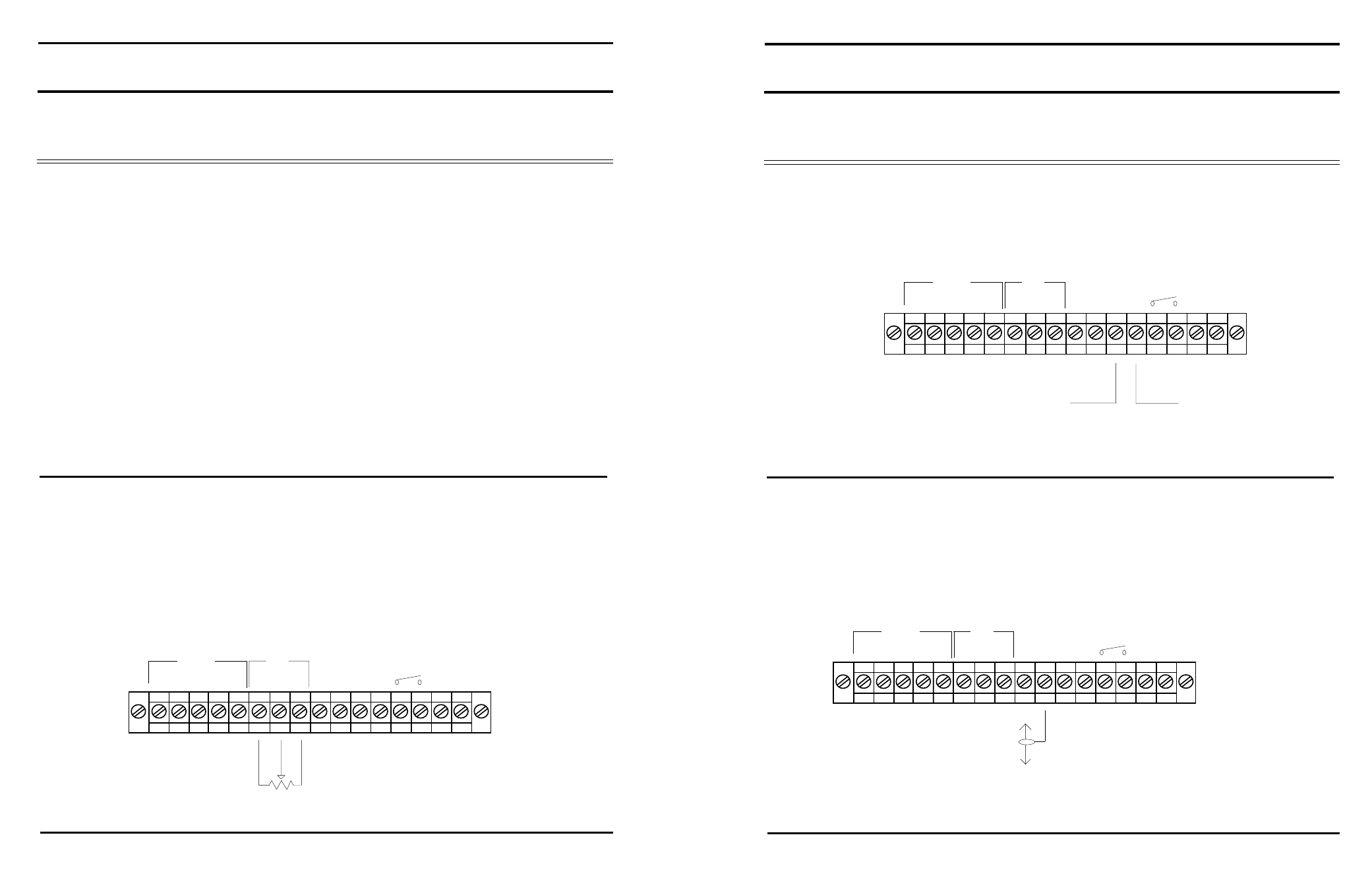
EFFECTS IN/OUT
MIX BUSS IN/OUT
Remove jumper from barrier terminal.
Wire effects unit to barrier terminal as shown.
LO
HI
SH
LO
HI
A
B
OUTPUTS
HI
ARM
LO
RMT
SUM
AFX
MUTE
AUX
IN
OUT
SH
IN
OUT
SW
IN
HI
SH
IN FROM EFFECTS UNIT OUTPUT
OUT TO EFFECTS UNIT INPUT
The summing buss link allows access to the summing buss thru a 10K resistor. This allows the link to
function as either an input, or an output, when used with unbalanced line level signals.
LO
HI
SH
LO
HI
A
B
OUTPUTS
HI
ARM
LO
RMT
SUM
AFX
MUTE
AUX
IN
OUT
SH
IN
OUT
SW
IN
HI
SH
SUMMING BUSS ACCESS, IN OR OUT