Rear view, Wiring table, B1 b2 – Protech Audio 5053B User Manual
Page 2: B1 b2 installation, Alignment
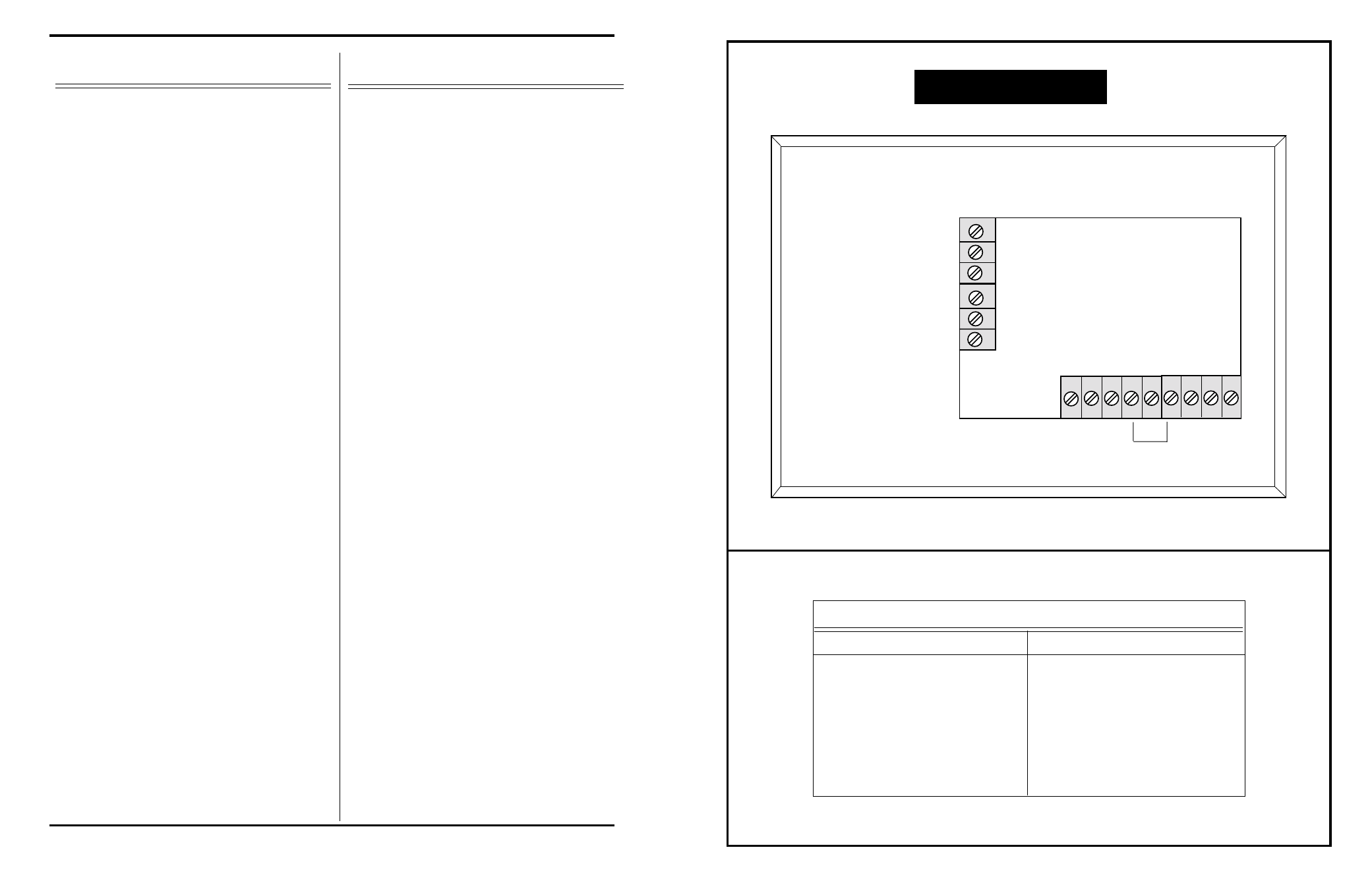
1 2 3 4 5 6 7 8 9
A
B
C
D
E
F
Strap For Phantom Power
REAR VIEW
PIN A = +24VDC
PIN B = GROUND
PIN C = BUSY BUSS
PIN D = SHIELD
PIN E = OUTPUT HI
PIN F = OUTPUT LO
PIN 1 Switch Closure
PIN 2 Switch Closure GND
PIN 3 N/A
PIN 4 +24VDC
PIN 5 N/A
PIN 6 Phantom Power Connection
PIN 7 GND
PIN 8 Audio Input LO
PIN 9 Audio Input HI
WIRING TABLE
B1
B2
INSTALLATION
Page 2
1/06
The Model 5053B Remote Microphone Station is designed to be
mounted in a standard triple gang electrical box at least two (2)
inches deep. Wiring to the box must include;
2 -
3 -
1 -
Step 1-
Step 1A-
Step 2-
Step 3-
ALIGNMENT
The alignment of the Model 5053B is a one step procedure.
The gain of the unit is factory adjusted for 45dB. This will
usually achieve proper level at the receiving device. It is not
recommended that the gain of the 5053B be lowered, since
this will result in a lower signal-to-noise ratio. If additional
gain is needed, simply turn the gain trimpot, accessible thru
the front panel, until the desired output level is achieved.
A 24 volt DC power connection, with the low side of the
power supply connection providing a good EARTH ground.
The minimum recommended gauge is 22AWG.
(Optional) A single conductor, 24AWG minimum, for the
busy buss
A two-conductor, shielded cable, 24AWG or heavier
Mount the microphone mounting clip on the front
panel
(Optional) Strap unit for phantom power (See
Wiring Diagram On Facing Page).
Wire one of the microphones to be used, and test
several Model 5053B units for correct operation with
the test microphone. It is recommended that this
step be done in the shop, before mounting the units
in the field.
Wire the audio output and 24VDC to one unit
(See Wiring Diagram On Facing Page), mount the
unit in the electrical box, plug-in microphone, and
test for audio outpt at the receiving device.
B1
B2