Installation instructions for qualified personnel, Installation – REMKO MXD 200 v.1 User Manual
Page 19
Installation instructions for qualified personnel
Important notes prior to
installation
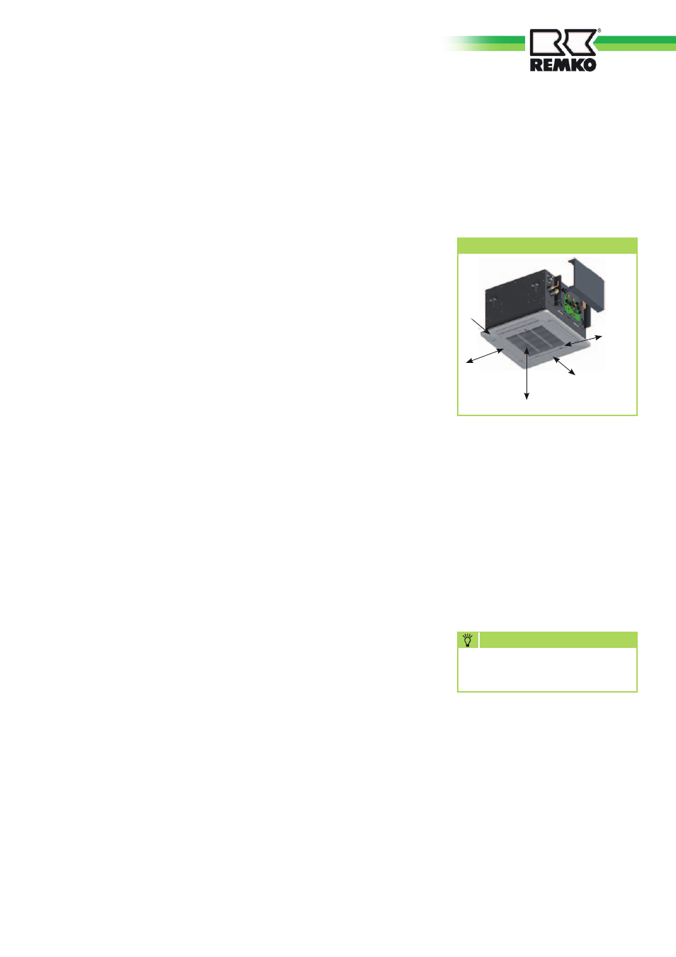
Minimum clearances
Observe the minimum clearances to
allow access for maintenance,
repair work and for
optimum air distribution.
Minimum clearances
All dimensions are given in mm
For installation of the entire sys-
tem, observe the operating instruc-
tions of the indoor unit and the
outdoor unit.
■
Transport the unit in its original
packaging as close as possible
to the installation location.
This avoids transportation dam-
age.
■
Check the contents of the
packaging for completeness
and check the unit for visible
transport damage.
Immediately notify any de-
ficiencies to the contractual
partner and forwarding agent.
■
Lift the unit at the corners and
not by the refrigerant or con-
densation connections.
■
The refrigerant pipes (injec-
tion and suction pipe), valves
and connections to make them
tight against vapour diffusion.
If necessary, also insulate the
condensation line.
■
Select an installation location
which allows air to freely flow
through the inlet and outlet (see
section "Minimum clearances")
■
Do not install the unit in the
immediate vicinity of devices
with intensive thermal radia-
tion. Installation near sources of
thermal radiation reduces the
output of the unit.
■
Install the refrigerant pipes from
the indoor unit to the outdoor
unit.
■
Seal off open refrigerant lines
with suitable caps or adhesive
strips to avoid the infiltration
of moisture and never kink or
compress the refrigerant pipes.
■
Only use the union nuts for the
refrigerant pipes included in
the delivery, and remove them
shortly before connecting the
refrigerant pipes.
.
■
Establish all electrical connec-
tions in accordance with the rel-
evant DIN and VDE standards.
■
Always ensure electrical cables
are properly connected to the
terminals, otherwise there is
a risk of fire.
■
Service openings should be pro-
vided in the suspended ceiling
to allow maintenance access to
the control box.
Installation material
The indoor unit is fastened using
a wall brace and 4 bolts (provided
by the customer).
In order to complete the installa-
tion, use the supplied installation
material. Appropriate dowels, trap-
ezoidal sheet metal supports, steel
profiles, fixing clips for refrigerant
and condensation pipes (as well as
laying ducts) and connection fit-
tings for condensation pipes must
also be provided.
Selection of the installation
location
The indoor unit is designed for
horizontal mounting in suspended
ceilings with Euroraster dimen-
sions. It can also be installed in
other types of suspended ceilings
with different dimensions.
Take into account the installation
height of the equipment.
1000
1000
1000
1000
Installation
Installation may only be per-
formed by authorised specialists.
NOTE
Unit installation
The unit is mounted on four thread-
ed rods with the cover face down.
Take into account the ceiling grid
and any other installations.
1. Use the dimensions of the ceil-
ing cassette to mark the fixing
points for the threaded rods on
structural parts approved to sup-
port the static load, and above
the suspended ceiling.
19