Assembling the oil burner, Initial operation – REMKO SLV11-88-2 User Manual
Page 5
5
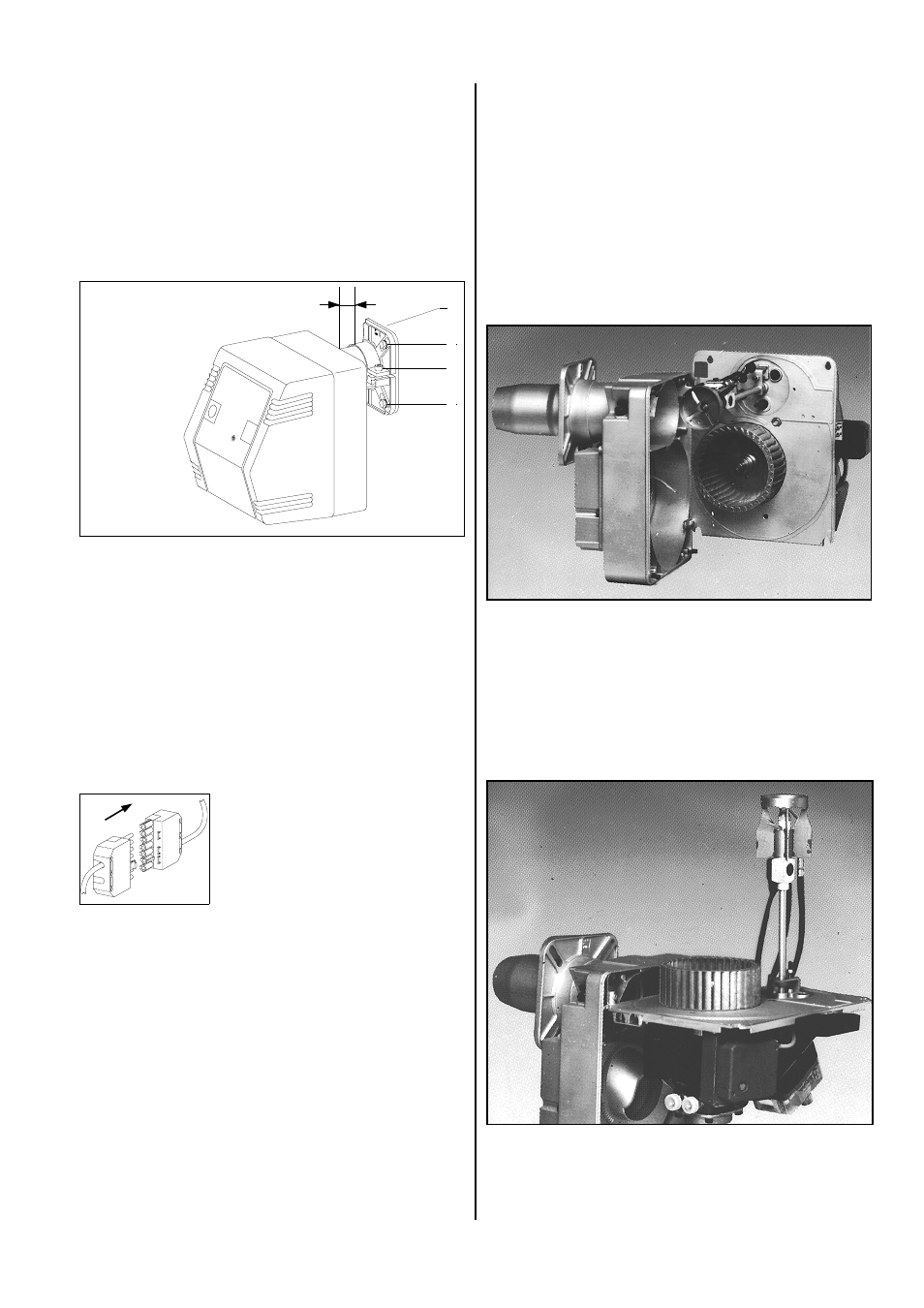
Assembling the Oil Burner
Assembling the burner flange and the burner
1. Place the flange seal 1 on the burner flange.
2. Attach the burner flange to the unit housing with the
four screws.
Pay attention to labels “OBEN“ (UP, HAUT)!
3. Tighten the two upper screws 2.
4. Tighten the lower screws 4 but not all the way so that
the burner flange can still be pulled together.
5. Slide the flame pipe of the burner into the burner
flange.
Observe dimension X in the diagram.
6. Clamp the flame pipe to the flange when the burner is
slightly lifted (3° incline).
Use an Allen key.
7. Finally, tighten the lower screws.
Forced-air burners with a heating capacity of more than
350 kW are connected to the 400 V power supply by a
separate line.
Initial Operation
Getting ready
After loosening the 4 housing screws, the assembly
base plate is removed from the housing and suspended
to the side.
For model sizes SL 44 – SL 66/2, 6 housing screws
must be removed (pay attention to the arrow).
The most important functional components for assem-
bly and maintenance are immediately accessible in ac-
cordance with the corresponding requirements.
Electrical connection
A standard 7-pin plug is usually
used for the electrical connection
to the warm air generator whose
socket is attached to the burner.
1
3
2
X
Burner up to model size 33: X = 20 mm
Burner up to model size 44: X = 30 mm
4
Oil connection
The supplied oil hoses are connected to the oil pump
and attached with the clamp.
The shut-off and filter mechanisms of warm air genera-
tors must be arranged in such a way that hoses can be
properly laid. The hoses may not be bent.
Flexible fuel lines in particular must be protected from
damage, for example, by forklifts, animals, etc.
G
The relevant installation instructions and the wir-
ing diagram of the burner must be followed!
G
The forced-air oil burner made only be put into op-
eration by authorised personnel!
The assembly base plate can also be suspended hori-
zontally for maintenance, installation and replacement
of the nozzle.
Proceed as follows:
1. Hold the assembly base plate horizontally.
2. Slide the right mount sideways into the suspension.
3. Suspend the left side up into the lug.