Electrical connection – REMKO DN 40 User Manual
Page 7
7
Electrical connection
All electrical installation work is to be
performed by specialist companies.
Disconnect the voltage supply when
connecting the electrical terminals.
Observe the VDE guidelines.
!
CAUTION
■
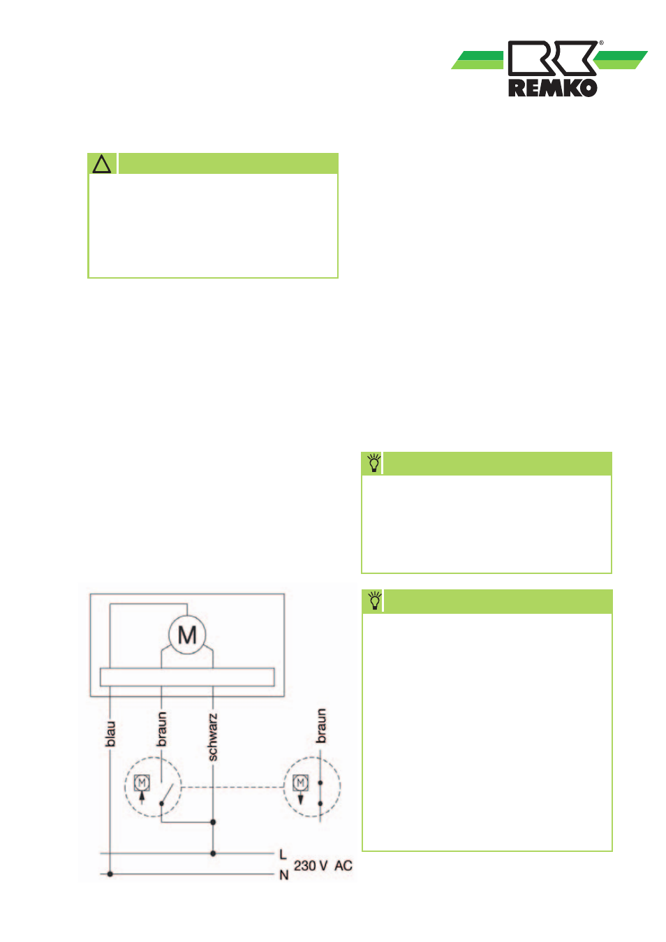
Limit switches are integrated in the
actuator of the 3-way switching
valve.
■
The actuator requires a continuous
operating voltage of 230V/1~/50Hz.
This must be connected to the black
(L) and blue (N) wires. In this state
the valve is in resting position. This
corresponds to heating position and/
or opening of the path I<->II.
■
The valve is actuated if the brown
wire of the actuator is additionally
connected to a voltage
of 230V/1~/50Hz. The valve
then moves downwards until
it reaches the limit switch. This then
corresponds to the position for hot
water / cooling / opening of the path
I<->III. The valve remains in this state
until the voltage from the brown wire
is switched off again.
■
Every heat pump has appropriately
labelled connection terminals for
the connection of the actuator.
Observe the instructions
in the installation manual of the heat
pump for the correct connection.
(Connection diagram and circuit
diagrams, if applicable)
NOTE
Hot water switching valve
Terminal block X1
No. 24 --- Black, live phase
No. 25 --- Brown, switching phase A3
No. 26 --- Blue, neutral conductor
Cooling switching valve
Terminal block X1
No. 28 --- Black, live phase
No. 29 --- Brown, switching phase A10
No. 30 --- Blue, neutral conductor
TERMINAL CONFIGURATION