Diagnostics - 8, Mapping mode - 9 – RLE LD5000 User Manual
Page 48
Chapter 12: System Configuration
User Guide: LD5000
40 970.484.6510
www.rletech.com
12-8 DIAGNOSTICS - 8
Menu selection 8 displays the LD5000 Diagnostics Menu. This menu is primarily used for troubleshooting
and system testing. The Diagnostics Menu is described in greater detail on page 64.
12-9 MAPPING MODE - 9
Option 9 displays the LD5000 Mapping Mode Menu. The mapping mode establishes a relationship
between a known physical location, such as a position on a floor map, and a distance reading as displayed
by the LD5000. Mapping is performed after all the cable is installed, the system is calibrated, and the
cable’s end-of-line-terminator is in place. Mapping makes locating a leak annunciated by the LD5000
much easier.
** LD5000 Help **
SC – LD5000 System Configuration
LS - Leak Status
SL - Silence Leak Relay
SF - Silence Fault Relay
SR - Silence All Relays
CA - Current Alarms
RA - Reset Alarms
UP - Update Alarms
AS - Alarm Silence (LCD)
AH - Alarm History
CH - Clear Alarm History
TD - Trend Data Table (Leakage Current)
CT - Clear Trend Data Table
TI - Display Date/Time
NS - Network Status (RS-485/Modbus)
MR - Reset Modbus Status (RS-485)
ND - Network Display (RS-485)
MT - Modbus Display
EX - Exit
SC
LD5000 System Configuration Menu
1. System Name: LD5000
2. Clock: 01/05/01 14:54:29
3. RS-485 Baud: 9600
4. Relays
5. Cable Feet/Meters: (Feet)
6. Calibration
7. LCD Setup
8. Diagnostics
9. Mapping Mode
10. Exit
Enter Menu Selection >
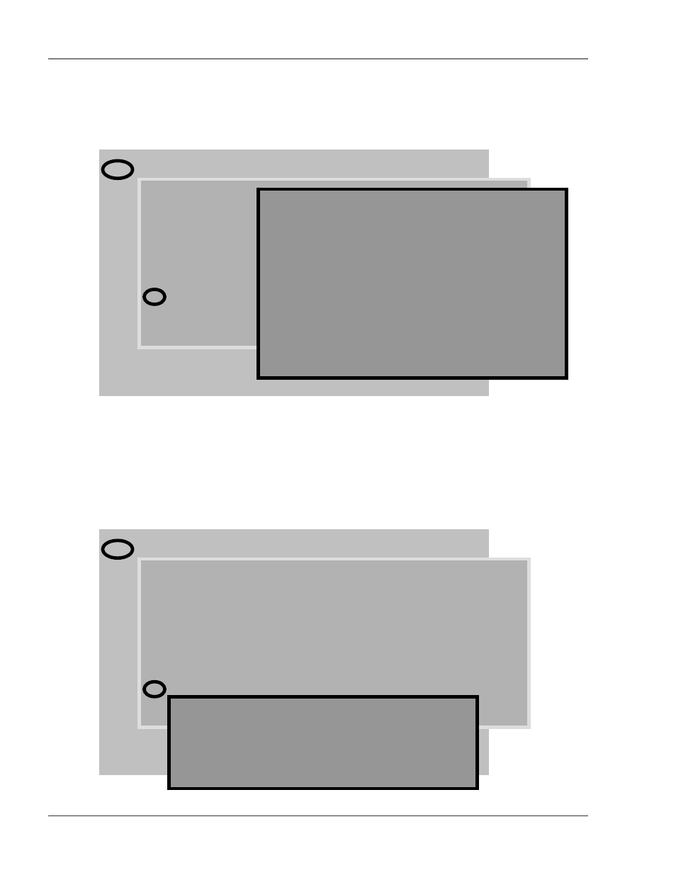
Enter Menu Selection >8
LD5000 Diagnostics Menu
1. Cable Readings
2. Dip Switch Readings
3. Force 4 to 20mA Output
4. Cable Relay On
5. Cable Relay Off
6. Output Leak Relay (K1) On
7. Output Leak Relay (K1) Off
8. Output Fault Relay (K2) On
9. Output Fault Relay (K2) Off
10. Relay Status
11. Exit
Enter Menu Selection >
Enter Menu Selection >9
LD5000 Mapping Mode Menu
1. Display Mapping Results
2. Begin Mapping
3. Exit
Enter Menu Selection >