Terminator enable/disable, Twisted pair, Sensor location – RLE GD200 User Manual
Page 4: Q5 installation drawing
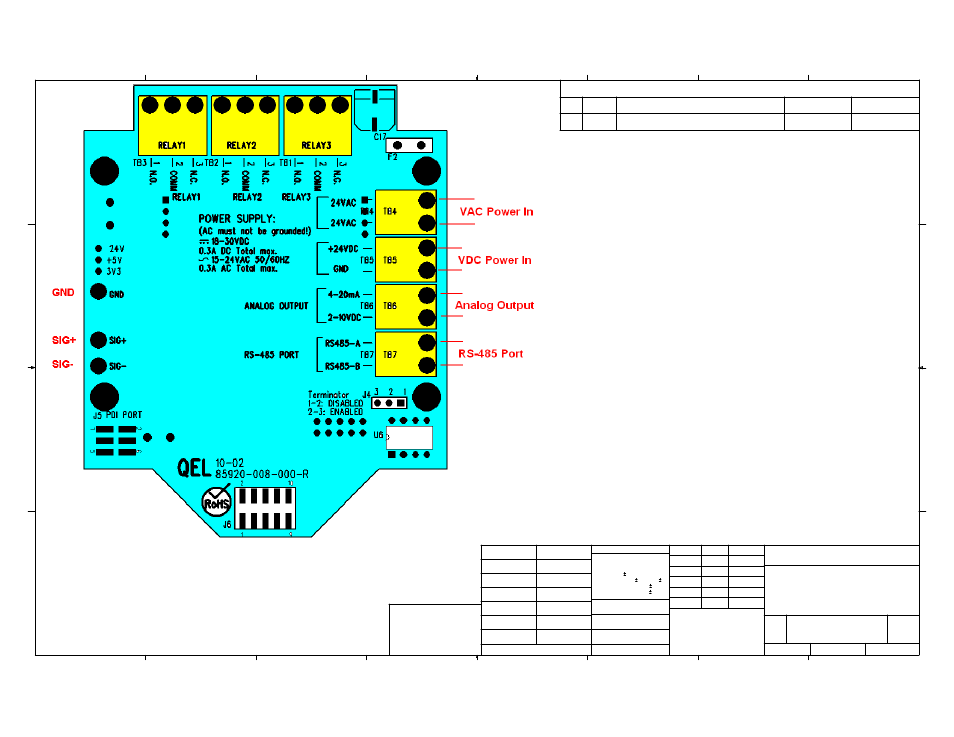
Q5
INSTALLATION DRAWING
Quatrosense Environmental Ltd
85950-002-000
D
C
B
A
A
B
C
D
1
2
3
4
5
6
7
8
8
7
6
5
4
3
2
1
THE INFORMATION CONTAINED IN THIS
DRAWING IS THE SOLE PROPERTY OF
<INSERT COMPANY NAME HERE>. ANY
REPRODUCTION IN PART OR AS A WHOLE
WITHOUT THE WRITTEN PERMISSION OF
<INSERT COMPANY NAME HERE> IS
PROHIBITED.
PROPRIETARY AND CONFIDENTIAL
NEXT ASSY
USED ON
APPLICATION
DIMENSIONS ARE IN INCHES
TOLERANCES:
FRACTIONAL
ANGULAR: MACH BEND
TWO PLACE DECIMAL
THREE PLACE DECIMAL
INTERPRET GEOMETRIC
TOLERANCING PER:
MATERIAL
FINISH
DRAWN
CHECKED
ENG APPR.
MFG APPR.
Q.A.
COMMENTS:
DATE
NAME
TITLE:
SIZE
B
DWG. NO.
REV
SCALE: 1:2
UNLESS OTHERWISE SPECIFIED:
B
XY
XY
XY
2010/02/25
2010/02/25
2010/02/25
SHEET 4 OF 5
DO NOT SCALE DRAWING
Terminator Enable/Disable?
The terminator on each end of the RS485 loop is designed to
match the electrical impedance characteristic of the twisted pair
loop, and will prevent signal echoes from corrupting the data on
the line. The terminator should be enabled on BOTH ends of the
RS485 loop. Short and medium length modbus/485 loops can
operate without the terminating resistor. Longer runs may require
the terminating resistors. But adding terminator dramatically
increases power consumption.
Twisted Pair?
RS-485 is designed to be a balanced system. The signal on one
wire is ideally the exact opposite of the signal on the second
wire. In other words, if one wire is transmitting a high, the other
wire will be transmitting a low, and vice versa. Although RS-485
can be successfully transmitted using multiple types of media, it
should be used with wiring commonly called "twisted pair."
Sensor Location:
Several factors should be considered when selecting locations to install
sensors. The following general suggestions should be considered to assure
the detection of the target gas. Select the most suitable location for each
sensor.
1. Air Currents: If there are fans, winds, or others sources of air movement,
gases may tend to rise to collect in certain areas of a facility. The local air
currents should be assessed to aid in selecting the sensor location. In outdoor
situations considerations such as prevailing winds should be accounted for.
Air convection can often be more important in determining gas concentrated
areas than factors of Vapor Density.
2. Vapor Density: For the target gas heavier than air. Detecting location
should be 9 - 18 inch (0.23m to 0.46m) above the floor.
3. Gas Emission Sources: As a rule, at least one sensor should be located in
close proximity to each point where a leak is likely to occur. This is particularly
important when a liquid having a low volatility is monitored.
4. Environmental Factors: Designed to rugged outdoor use consider the
following in selecting locations. Install sensors where they will be protected
from wind, dust, snow, water, vibration and shock.
REVISIONS
ZONE
REV.
DESCRIPTION
DATE
APPROVED
-
-
See Sheet1
-
-