Contd.) – SL Power Electronics GPHP600 User Manual
Page 2
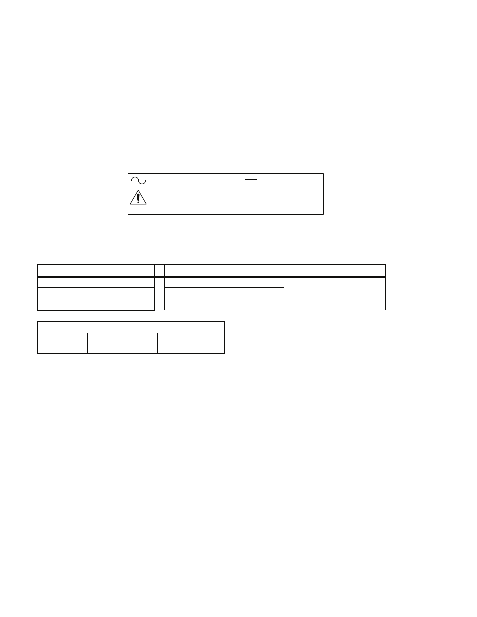
EXPLANATION OF SYMBOLS
Direct Current
Attention, Consult
Accompanying Documents
Alternating Current
GPHP600/700 SERIES
INSTALLATION INSTRUCTIONS
(Contd.)
WARNING! RISK OF FIRE! A blown internal fuse is an indication of catastrophic failure of circuit component(s). Repair
must be performed by Condor authorized personnel.
RACK MOUNTING: The GPHP600/700 series is designed to be rack mountable and comes with a mounting handle and
attaching hardware, but can be mounted as a built-in component.
AIRFLOW/COOLING: The GPHP600/700 series is designed with two integral fans that are rated 54 cfm total.
C O N N E C T I O N S
Connector: ERNI Type H15 P/N 123767 or AVX ELCO 108456015001169 DIN 41612 Style H15
AC INPUT
STATUS and CONTROL
Line
Z32
AC Power Fail
D22
Neutral
D30
DC Power Good
Z20
Reference to Common
Ground
Z28, D26
Inhibit
Z24
DC OUTPUT
Z12, D14, Z16, D18
Main Output
Output #1
Z4, D6, Z8, D10
Rtn (Common)
Condor DC Power Supplies Inc. will not be liable for the safety, reliability or performance of these power supplies if a) any changes, modifications or repairs are
carried out by other than authorized agents of Condor DC Power Supplies Inc., or b) the installation of the supply is not in accordance with these installation
instructions and the applicable UL, CSA, and EN/IEC safety standards.
41-35343-0001, Rev A 8/4/04