SL Power Electronics GSM15 User Manual
Page 2
GSM15 SINGLE OUTPUT SERIES INSTALLATION INSTRUCTIONS
GROUNDING, MOUNTING and ISOLATION: Safety grounding is not required. Grounding the
supply will result in improved EMI performance and increased earth leakage current. For reduced earth
leakage current, do not use earth ground connection. Request product specifications for details.
Grounding the unit is achieved by bonding the hole in the PWB near C4, identified by the Ground
symbol, to earth with a wire soldered to the terminal. Alternatively, metal attaching hardware can be
used.
For Class II operation (no earth connection), insulating type hardware must be used in the mounting hole
near J1.
Creepage distances from Primary to Secondary are 8 mm and from Primary to Ground are 4 mm.
Clearance distances from Primary to Secondary are 5 mm and Primary to ground are 2.5 mm. Secondary
to Ground Creepage and Clearance distances are not controlled. These Creepage and Clearance
distances must be maintained after installation to preserve their intended safety.
TEMPERATURES: The maximum operating temperatures of certain safety components, as defined in
the applicable safety standards, must not be exceeded after installation to preserve the intended safety.
The output power, ambient air temperature and the availability, amount, direction and/or restriction of
airflow influence the temperatures of these components.
FUSING: Fusing is provided on the Line side of the AC Input. A Neutral fuse must be added for
medical use. A blown fuse is an indication of catastrophic failure of circuit component(s). Repair must
be performed by Condor authorized personnel. Refer to fuse markings on unit for type and rating.
WARNING! SHOCK HAZARD! Dangerous voltages are present on some components, printed wiring
traces and heatsinks.
AGENCY MARKINGS: Agency marking will not be found on the power supply. They will be found
on the shipping carton only.
CONNECTIONS
SL Power Electronics Corp. will not be liable for the safety, reliability or performance of these power supplies if a) any changes, modifications or repairs are carried out by other than
authorized agents of SL Power Electronics Corp., or b) the installation of the supply is not in accordance with these installation instructions and the applicable UL, CSA, and EN/IEC
safety standards.
41-34957-0001 Rev. D
Page 2 of 2
J1
AC Input
J2
DC Output
MATING CONNECTORS
1
AC Line
1, 2 Common
J1, J2: AMP MTA-100 Receptacle
4
AC Neutral
3, 4 + Output
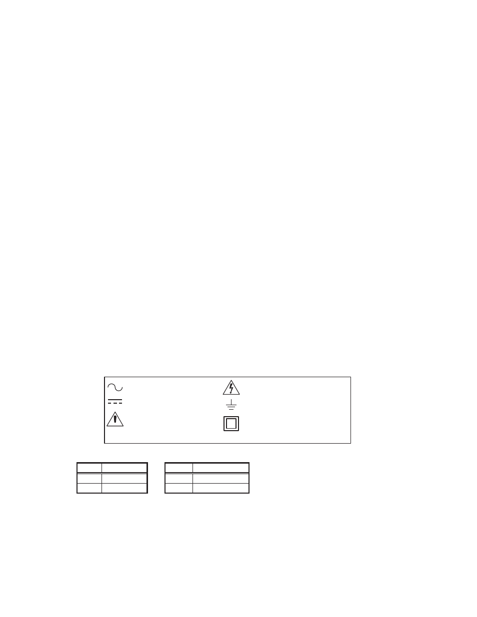
EXPLANATION OF SYMBOLS
Class II Equipment
Earth (Ground)
Attention, Dangerous Voltages
Alternating Current
Direct Current
Attention, Consult
Accompanying Documents