Sloan 910 Royal Exposed 900 Hydraulic Series User Manual
Sloan For Home
Code No. 0816300
Rev. 4 (05/13)
INSTALLATION INSTRUCTIONS FOR SLOAN SERIES 900 HYDRAULIC
FLUSHING SYSTEM — EXPOSED CLOSET, URINAL AND SERVICE SINK
LIMITED WARRANTY
Unless otherwise noted, Sloan Valve Company warrants this product, manufactured and sold for commercial or industrial uses, to be free from defects in material and
workmanship for a period of three (3) years (one (1) year for special finishes, SF faucets, PWT electronics and 30 days for PWT software) from date of first purchase. During
this period, Sloan Valve Company will, at its option, repair, replace, or refund the purchase price of any product which fails to conform with this warranty under normal use and
service. This shall be the sole and exclusive remedy under this warranty. Products must be returned to Sloan Valve Company, at customer’s cost. No claims will be allowed for
labor, transportation or other costs. This warranty extends only to persons or organizations who purchase Sloan Valve Company’s products directly from Sloan Valve Comapny
for purpose of resale. This warranty does not cover the life of the batteries.
THERE ARE NO WARRANTIES WHICH EXTEND BEYOND THE DESCRIPTION ON THE FACE HEREOF. IN NO EVENT IS SLOAN VALVE COMPANY RESPONSIBLE FOR ANY
CONSEQUENTIAL DAMAGES OF ANY MEASURE WHATSOEVER.
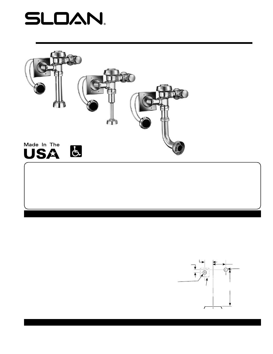
Exposed Closet Flushometer
1½” (38 mm) Top Spud
MODEL 910/911
MODEL 913
MODEL 915
MODEL 916
Exposed Closet Flushometer
1½” (38 mm) Back Spud
MODEL 920
MODEL 921
MODEL 922
Exposed Urinal Flushometer
1 ” (32 mm) Top Spud
MODEL 980
Exposed Urinal Flushometer
¾” (19 mm) Top Spud
MODEL 986
Exposed Service Sink Flushometer
1½” (38 mm) Top Spud
MODEL 917
Model 910/911
Model 986
Model 920
CENTERLINE OF FIXTURE
TOP OF FIXTURE
SEE VALVE
ROUGH-IN
WATER
SUPPLY
LINE
4-3/4” (121 mm)
4” x 4”
(102 mm x 102 mm)
BOX OPTIONAL -
FURNISHED BY OTHERS
VALVE ACTUATOR
LOCATION
1-1/2” (38 mm)
DIAMETER HOLE
1-1/2” (38 mm) ‡
2-9/16” (65 mm) ‡
SUPPLY AND ACTUATOR ROUGH-IN
‡ Dimension must be
held to 1/8” (3 mm).
PRIOR TO INSTALLATION
Prior to installing the flushometer, install the items listed below as illustrated in
the Rough-in Diagrams on Page 2.
• Install closet or urinal fixture.
• Install 1-1/2” (38 mm) drain line (NOT supplied by Sloan).
• Bore a hole (see rough-in for size) in wall for water supply line, and install
water supply line.
• Bore 1-1/2” (38 mm) holes in wall for both the Hydraulic Push Button
Actuator and the Valve Actuator.
• For Model HY-72-A Push Button Actuator, install an electrical box at both
Push Button Actuator and Valve Actuator. Run conduit between the two
electrical boxes.
IMPORTANT:
• INSTALL ALL PLUMBING IN ACCORDANCE WITH APPLICABLE CODES
AND REGULATIONS.
• WATER SUPPLY LINES MUST BE SIZED TO PROVIDE AN ADEQUATE
VOLUME OF WATER FOR EACH FIXTURE.
• FLUSH ALL WATER LINES PRIOR TO MAKING CONNECTIONS.
Sloan’s flushometers are designed to operate with 10 to 100 psi (69 to 689
kPa) of water pressure.
THE MINIMUM PRESSURE REQUIRED TO THE VALVE IS
DETERMINED BY THE TYPE OF FIXTURE SELECTED.
Consult fixture manufacturer
for minimum pressure requirements.
Most Low Consumption water closets (1.6 gpf/6.0 Lpf) require a minimum
flowing pressure of 25 psi (172 kPa).
IMPORTANT: With the exception of Control Stop Inlet, DO NOT use pipe thread
sealant or plumbing grease on valve components or couplings!
TOOLS REQUIRED FOR INSTALLATION
• Straight blade (flathead) screwdriver
• 5/64” hex wrench
• Parker Tube Cutter (PTC)
• Sloan A-50 Super-Wrench™, Sloan A-109 Plier Wrench or smooth
jawed spud wrench