Space Ray RSCA Series User Manual
Page 11
Form #43219000
Sept 2012
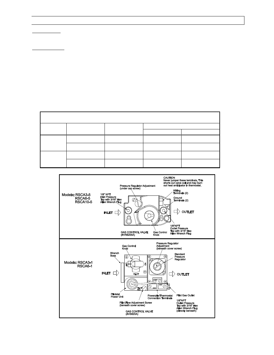
10) INSTRUCTIONS FOR PRESSURE TEST GAUGE CONNECTION
Supply Pressure
1. The installer will provide a 1/8" N.P.T. plugged tapping, accessible for test gauge connection immediately
upstream of the gas supply connection to the heater.
Manifold Pressure
1. Turn the gas valve to the "OFF" position. Remove the 1/8" plug from the manifold downstream from the
combination gas valve at one of the outlet pressure taps and connect a 1/8" nipple to the tapped hole.
Connect the gauge to the nipple. Turn on the gas supply.
2. With the main burner operating, check the burner manifold pressure using a water manometer. Gauges
that measure pressure in pounds per square inch are not accurate enough to measure or set the
manifold pressure. All measurements MUST BE made when this heater and all other gas burning
equipment that is connected to the gas supply system are operating at maximum capacity.
3. The combination gas valve is factory set and should not require adjustment. If full rate adjustment is
required, remove the cover screw. Using a small screwdriver, turn the adjustment screw clockwise
to
increase or counterclockwise
to decrease the gas pressure to the burner. Replace the cover screw.
The gas pressures are shown in the following table:
GAS PRESSURE TABLE
Model
Gas Type
Manifold Pressure
Supply Pressure
Minimum
Maximum
RSCA3
Natural Gas
3.5” W.C.
4.5” W.C.
14.0” W.C.
Propane Gas
10.0” W.C.
11.0” W.C.
14.0” W.C.
RSCA6 and
RSCA10
Natural Gas
6.0” W.C.
7.0” W.C.
14.0” W.C.
Propane Gas
10.0” W.C.
11.0” W.C.
14.0” W.C.
Minimum permissible gas supply pressure for purpose of input adjustment.
10