Advanced installation topics – Studio Technologies 50 2004 User Manual
Page 17
Model 50/51 User Guide
Issue 6, September 2004
Studio Technologies, Inc.
Page 17
Advanced
Installation Topics
Model 35 Stand Mounting
Included with each Model 35 Talent
Amplifier is a nifty mounting adapter that
allows the unit to be conveniently attached
to a microphone stand. Please refer to the
Installation Guide provided in the Model
35’s shipping carton for details.
Model 38 and Model 51 Mounting
Options
The Model 38 Talent Amplifier and the
Model 51 Control Console include provi-
sions for mounting to microphone stands,
equipment consoles, etc. To avoid
“reinventing the wheel,” our products are
compatible with the 25 Series components
from OmniMount Systems, a supplier of
finely engineered mounting systems. This
firm makes many versions of the 25 Series;
one of which should fit your needs. If you
desire microphone stand mounting the fol-
lowing components would be appro-priate
for English-thread applications: 25RST-25H
Straight Tube Reverse Mount with Quick
Release, along with a 25MA Microphone
Stand Adapter. (If quick adjustment is not
required the 25RST Straight Tube Reverse
Mount can be used in place of the first
item.) When connecting to metric-thread
stands please contact OmniMount
for the correct part numbers.
The bottom surface of the Model 38 Talent
Amplifier contains two threaded inserts
that will accept English-standard ¼
-20
screws. Using two,
5
/
8
-inch long, round-
head machine screws, the 25 Series clamp
assembly can be directly attached. The
cover of the Model 38 does not have to
be removed.
The design of the Model 51 did not allow
the inclusion of threaded inserts, so holes
of adequate size to allow
¼
-20 round head
machine screws are provided. It is intend-
ed that screws of
5
/
8
-inch length, along
with lock washers and machine nuts, will
securely attach a 25 Series mounting
clamp assembly. The cover of the Model
51 will have to be removed to gain ac-
cess to mounting holes. Be careful when
selecting the mounting screws—exceed-
ing the recommended
5
/
8
-inch length will
cause the mounting screws to damage the
Model 51’s internal components.
Remote Control Inputs
The Model 51 allows you to connect two
external switches or contact closures to
enable system functions. Input 1 allows
either a remote talk to studio or a remote
control room source select function to be
implemented. Input 2 allows a remote talk
to phones function to be implemented.
Using the remote “talk to” functions, it may
be useful to install switches at a producer
or director location. The Model 51 con-
tinues to provide local talk to studio and
talk to phones access even when external
switches are connected.
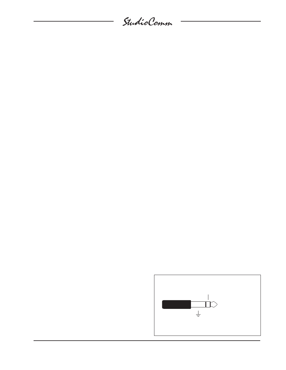
The required connector is a ¼
-inch
3-conductor phone plug. Tip is talk to
studio or control room source select, ring
is talk to phones, and sleeve is common.
External Communications Switches
Sleeve: Ground
Tip: Talk to studio
Ring: Talk to phones
(Switchcraft No. 297, Neutrik NP3C, or equivalent)