Interface – Sundance SMT338 User Manual
Page 16
Version 1.5
Page 16 of 19
SMT338 User Manual
5. Interface
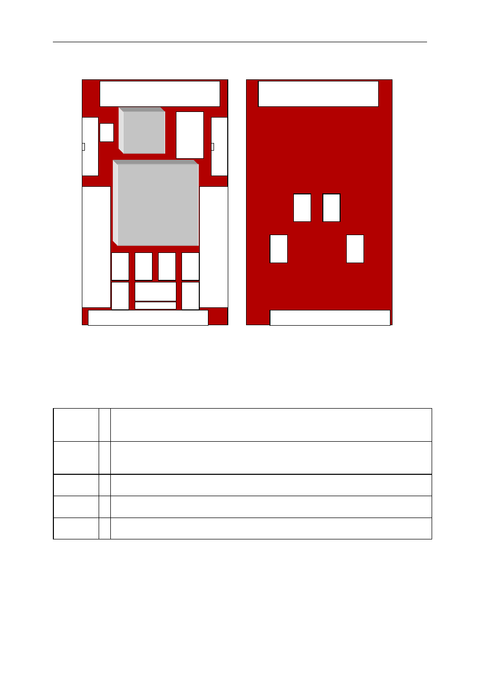
Figure 7: SMT338 Layout
Table 2 shows the Physical Layout of the SMT338, indicating the external connectors with
their location and numbering.
Connector definitions are as follows:
SDB 1,2 : Digital Data & Clock Input /Output Signal – Sundance Digital Bus High
Density ODU connector A (40-way High Density IDC Connectors).
DIFF1,
DIFF2
Differential Signals –50 WAY SCSI Male connectors. Solder Pins.
JTAG
: JTAG Signals – 6-way connector.
P1
: Top Primary connector.
P2
: Bottom Connector. (Bottom Primary and Global Expansion Connectors)
Table 2: SMT338 connector reference table
J
T
A
G
P2
P1
P1
P2
5 LE
DS
SDB Conn1
VIRTEX FPGA
XCVxxx
BG352
CPLD
95144
50-way
high
density
connecto
r
DIFF2
50-way
high
density
connecto
r
DIFF1
Driver
SDB Conn2
Receiver
Receiver
Receiver
Driver
Receiver
Receiver
Receiver
Receiver
Receiver
Voltage
Regulator
JTAG Connector
Osc