Thermo Technologies USDT 2005 User Manual
Page 3
2
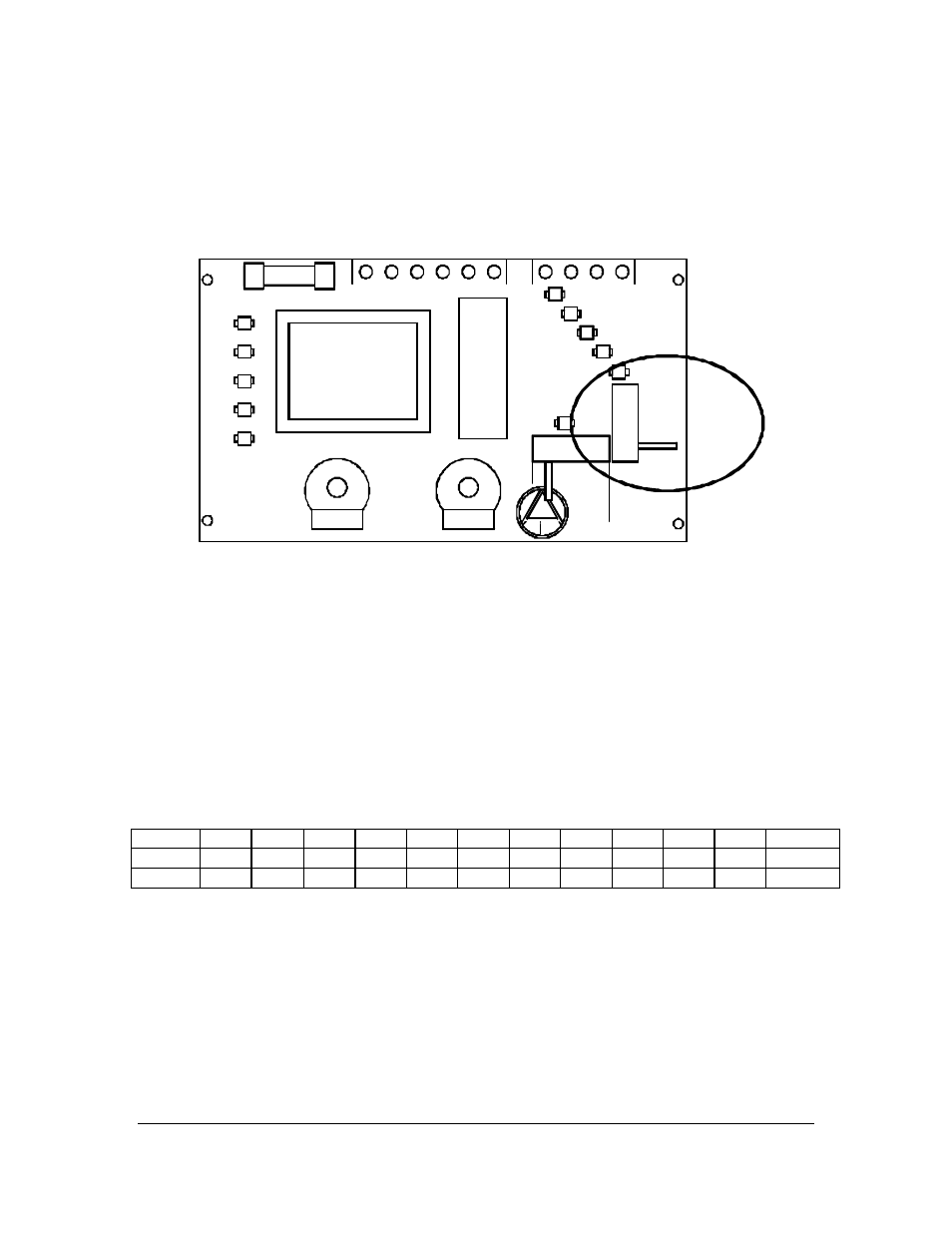
Selection of Operation Mode
If you are using USDT 2005 for a solar system, you don’t need to change anything. To use the
unit as a boiler controller, change the miniature switch level to the desired position as shown
below. The switch is located on the right side of the circuit board:
S+K
S+P
L+K
L+P
ANS 21
Change the switch position only when the unit is not energized. It is possible to damage
the control unit if the mode change is performed under voltage.
Switch Positions:
•
S+K
Solar systems with KTY (2000 ohm) sensors
•
S+P
Solar systems with PT 1000 (1000 ohm) sensors
•
L+K
Boiler control with KTY (2000 ohm) sensors
•
L+P
Boiler control with PT 1000 (1000 ohm) sensors
The impedance characteristics of sensors temperature dependencies are represented in the
following table:
T
0
10
20
25
30
40
50
60
70
80
90
100°C
R(KTY)
1630
1772
1922
2000
2080
2245
2417
2597
2785
2980
3182
3392
Ω
R(PT)
1000
1039
1078
1097
1117
1155
1194
1232
1271
1309
1347
1385
Ω
PECIFICATION
Supply Voltage
120 V AC
Fuse
3.15 A
Phantom Load
max. 2 W
Hysteresis
6 degrees
Delta T
4 – 24
o
F
Overheating Range
100 – 200
o
F
S