Thermo Technologies USDT 2005 User Manual
Page 5
4
l
Collector sensor (red cable with protective terminal box): Insert the sensor jacket into a
thermowell (sensor pocket), or strap it to the collector outlet pipe (flat plat collectors) that projects
from the collector housing. The best practice is to install a suitable sensor pocket into a T-piece
on the collector return outlet, to house the collector sensor. Protect sensor cable from UV and
moisture.
l
Storage tank installation (white cable): The sensor required for the solar loop is installed
in the lower part of the storage tank. If there is no provision for a tank sensor, it is advisable to
push the sensor beneath the insulation – keeping it close to the inner tank wall at the desired tank
location.
l
Pool sensor installation: Place a heat conductive T-piece on the suction line directly at the
pool outlet and screw in the sensor with an immersion sleeve (check corrosion resistance of the
material used). Another possibility would be to attach the sensor at the same place with clips or
adhesive tape, using appropriate thermal insulation against environmental influences.
l
Sensor cable extension: Sensor cables (22/4 AWG telephone cable) can be extended up
to 150 ft. A connection between the sensor and extension can be established as follows:
Cut supplied heat shrinkable tubing to desired length (about ½ ”). Slide tubing over one end of
wire to be sliced after removing enough outer insulation to accept the tubing. Then splice wire
and slide tubing over the splice. Heat gently all around until tubing shrinks tight.
Slide larger tubing (about ¾ “) over the entire completed splice. Heat gently all around until tubing
shrinks tight. This connection can then be drawn gently into the pipe work. You need only two
wires for sensor cable; the other two wires are spare wires. Do not overheat tubing! Remove heat
as soon as tubing shrinks tight, as material will continue to shrink. With flame source, use even
back and forth motion all around tubing. A heat gun may be used, if available. Let tubing cool for
maximum strength.
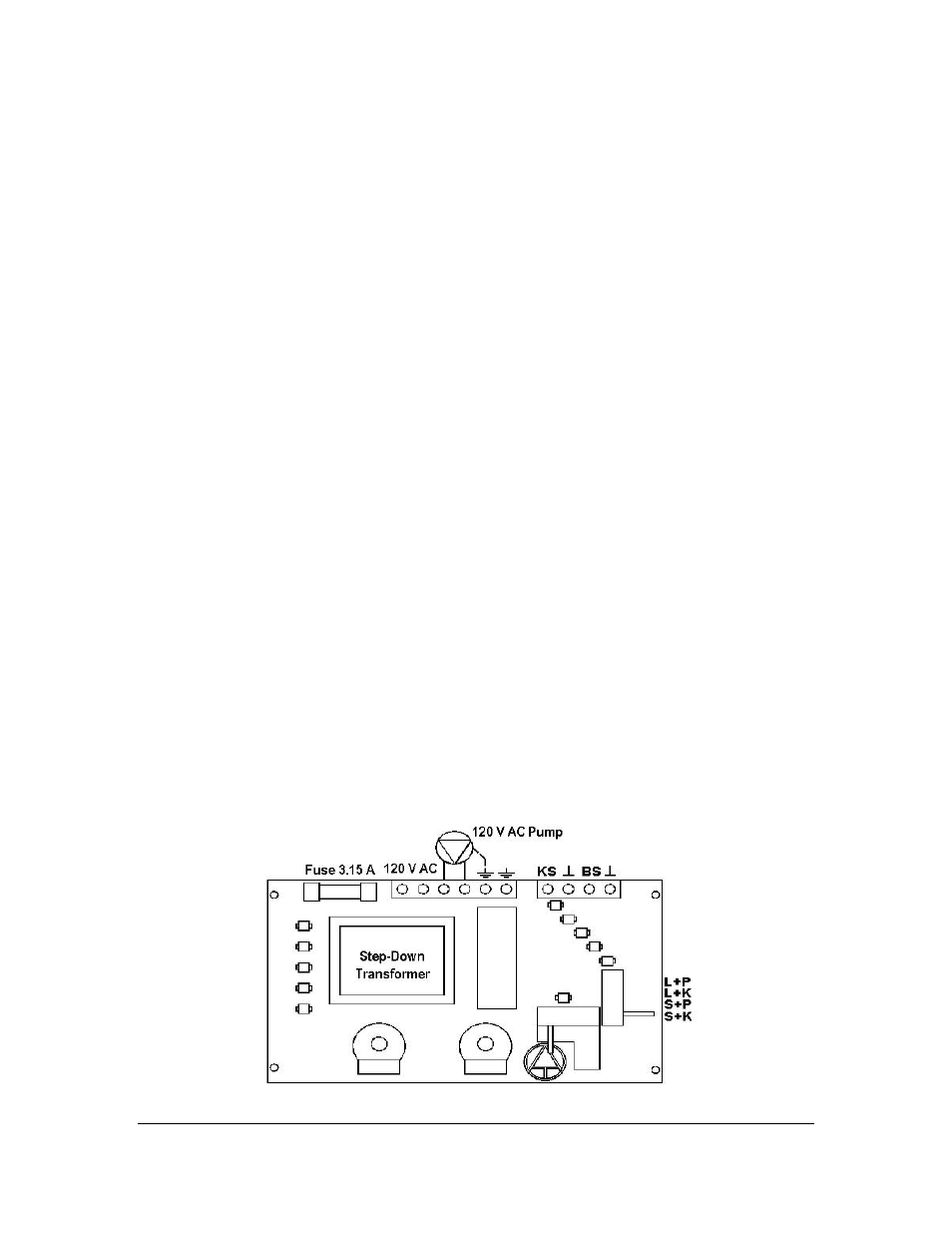
ontroller unit installation: For viewing comfort, the controller unit should be
positioned at eye level. It is always good practice to keep electronic equipment away
from cold, and heat, as extremes of temperature may reduce the lifetime of the device. It is also
good practice to keep electronic equipment away from heavy electrical loads, switches or
contactors as these may cause electrical and electromagnetic interference when switched on or
off.
Base of the unit to be mounted at the eye-level and wired as shown above
C