Thunder Tiger GT5.2 User Manual
Thunder Tiger Hardware
Features
Very precise electric 3axis stabilization system
OLED Display with Icon based User Interface
Wear resistant „Touch-Pad“ for easy handling without the need for
additional hardware
Supports standard PPM receivers, Spektrum DSM2/DSMX & JR remote
satellite receivers and singlewire connection of Futaba S-Bus, Graupner
SUMD, BEASTX SRXL and PPM singlewire connection
Suitable for Futaba and JR Servo- & RC-plug systems
Compact size and lightweight
High-quality Aluminum Case for optimal heat dissipation
No.8089
3-axis
Flybarless System
Introduction / Safety notes
Specifications
96 x 64 pixels OLED
Touch Pad
32-Bit High Speed Processor
MEMS gyros with ± 1000°/sec for X-Y-Z axis
1500us/970us/760us
65Hz – 333Hz (571Hz with 760us)
50Hz – 250Hz
mCCPM and 90°, 120°, 135° (140°) eCCPM
29,5 x 32 x 16mm
15g without wiring
4.8V~8.4V
Display
Input
CPU
Sensor-Speed
Tail servo pulse width
Tail control frequency
Swash plate frequency
Swash plate types
Dimensions
Weight
Operate Voltage
Manual
1-3 RC-Cable
Foam Pads
GT5.2
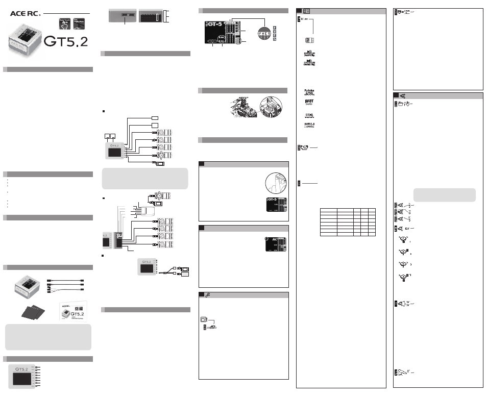
GT5.2 package contents
Note:
The supplied foam pads are very hard but normally suited for all kinds of
helicopters. For some nitro powered helicopters or in general helicopters
with a high vibration level the use of softer pads is recommended. But be
aware that soft pads may cause the unit to sway and thus cause
malfunction of the GT-5 unit.
!
Connectors
Imp2
Term
Imp1
Ail-r
Ele
Ail-l
Tail
Throt
8
7
6
5
4
3
2
1
Standard receiver / Channel 5 output
Standard receiver / PC
Standard receiver / Singlewire input
Aileron servo (right)
Elevator servo
Aileron servo left / Pitch servo (mCCPM)
Tail servo
Throttle servo / ESC
+
GND-
Pulse
Connectors for 2,4GHz Spektrum remote satellite receiver. One or two
receivers can be used. Always use receivers of same type (DSM2 or
DSMX)!
Note:
The connector No.7 (term) has pulse input/output on all 3 pins. Use the
1-3 cable to connect a standard receiver. Never connect a power source
to connector No. 7!
Spektrum remote satellite receivers can be directly connected to the GT5. The
GT5 is working as the main unit to which you just have to connect the servos.
Also you can use GT5 with singlewire systems like Futaba S-Bus, Graupner
SUMD, BEASTX SRXL or PPM singlewire. In this case you just have to connect
the wire from the receiver to connection imp1 or imp2 (in case PPM
singlewire is used). Because these technologies constantly evolve we cannot
guarantee full compatibility. For this reason the operation is at your own risk.
To prevent damage of the servos it is recommended to not connect the servos
and servo linkages unless you did perform initial setup. When using the BEC
of an electronic speed controller to power the system make sure the motor
can not start by accident. To prevent the controller from getting configured
incorrectly due to wrong signal output it also is recommended to not connect
the speed controller and use a separate receiver battery instead unless you
did complete receiver setup and gain full control over GT5's throttle output!
Connection to receiver/satellites
Spektrum/JR Satellite Receiver or
Futaba S-Bus
Satellite
Receiver
dsm
dsm
SER
VO
SER
VO
SER
VO
SER
VO
ESC / BEC
S- bus
Receiver
Channel 5 output:
Example: Governor
signal cable on nitro helis
and/or remote glow igniter.
To avoid causing damage to the servos, do not connect the servos
until after the servo set-up procedure has been carried out step 5
& 6. To begin with, simply connect the GT5 directly to a 4.8Volt Rx
battery, or regulated 6Volt power supply, into the Ch1 (Throt) port.
On electric machines, make sure the ESC/BEC is set-up correctly
before connection to the GT5.
!
Initial Set-up
For the moment it is recommended to disconnect all servos. Only receiver
and power source should be connected. When using the BEC of your electric
speed controller to power the unit, it is recommended to disconnect the
motor from the controller to prevent the motor from starting by accident.
Installation
GT5 can either be
mounted flat on the
top or bottom of the
heli (eg. on the gyro
platform) or vertical
(preferably on the side
of the frame of the
helicopter).
It is only necessary that the pin connector and the cables must be aligned
with or against the flight direction. The plugs of the cables must not show
laterally out from the GT5. In addition, the edges of the housing of GT5 must
always be aligned parallel to the three axes of the helicopter.
1
1) The three bold bars show sensor movement – Aileron, Elevator and
Rudder.
2) GT5 will scan receiver type when initial. It will show receiver type,
if it shows " -- " means there is no receiver or wrong receiver type.
3) Voltage display Upper value: Voltage actually
Lower value: Lowest voltage(break-in)during flight
4) The numbers show channel information for each function. When sticks in
the transmitter are centered, the channels should be 0
5) The two numbers show swash gyro gain and tail gyro gain in percent.
These values never can get below 50 and above 150.
Standard receiver
Aileron
Rudder
Gain
Pitch
Elevator
This pin could be connected to battery
Throttle
SER
VO
SER
VO
SER
VO
SER
VO
(for Nitro)
SER
VO
ESC
Receiver
Connecting battery / BEC
ESC
BATTERY
If you use the GT5 with an
electric helicopter and you
have a speed controller with
integrated BEC it's not
obligatory that you use an
external receiver battery.
Please pay special attention to the capability of your power supply as with
flybarless helicopters the peak power consumption of the servos can be
very high. With some BECs the voltage during hard flight may drop
dramatically and cause total system failure resulting in crashing the
helicopter. If the BEC allows to, using a buffering battery with equal voltage
level is mandatory. Consult the manual of the ESC and ask the
manufacturer for further assistance and capability of the BEC. If in doubt
using a separate power supply is recommended.
The swash plate mixing is done by the GT5. In the transmitter you must
choose as swash plate type „mechanical Mixing“ (mCCPM) or „1 servo for
each function“. You MUST NOT choose a swash plate type like 120° or 140°.
Make sure all servo throws (ATV) are set to -100 and +100 (standard
configuration for all transmitters) and all servo centers and trims are set to 0
(in all flight modes!). For initial setup the pitch curve also has to be set from
-100 to +100 (after the configuration of GT5 you can set different pitch
curves in your transmitter).
When using GT5 in combination with a standard receiver you need, besides
the 4 channels for the control functions and the channel for the throttle, a
sixth channel that controls the tail gyro gain. For this you may use your
transmitter's gyro menu or simply a dial or knob.
When using GT5 in combination with Spektrum remote satellites or a
singlewire receiver it is possible to adjust tail gyro gain and also swash gyro
gain. These can be controlled by two separate channels, one common channel
or you also may do without gain adjustment at all. Whatever you decide to,
make sure the transmitter is prepared for it.
As throttle signal is only passed through the unit in singlewire application
respectively is directly connected to the receiver, throttle is the only
parameter, that has not be treated specially. So adjust your throttle curves
however you like. Please note that for performing function assignment when
using a singlewire receiver it may be necessary to deactivate the throttle
channel, e.g. by using the autorotation switch.
Transmitter setup
Display
Pitch
Aileron
Elevator
Rudder
2
3
1
5
4
After powering up you will at first see the receiver
scan. If GT5 does not detect any receiver or shows
“not equal”, this is not of importance for the moment.
It may be necessary to program the correct receiver
type first.
Then you will see gyro initialization, during this time
“Do not” move the unit as GT5 tries to calibrate zero
positions of the gyro sensors (it is not important that
the heli is standing level to the ground, only it mustn't
be moved).
Finally you will see the main screen of GT5 as already
shown above. To interact with the unit touch with your
finger to the touchpad on left side of the housing. A
small cursor will appear on the left side of the display
in the area of your finger.
Starting GT5
1
If you move the cursor upwards to the ACE-RC Logo
and hold it there for 3 seconds, you will enter the
programming menu of GT5. To select a menu entry
or confirm a value tap the touchpad with your finger
twice. To move up/down in the menu or to
increase/decrease values slide with the finger
2
Entering programming menu
upwards or downwards on the touchpad.
Programming menu is divided into two main sections: “control” and
“setup” section. These two sections are indicated by the black and white
bar on the very left side. When entering programming menu you will be
located in control section at PID control menu which will be used very
often in later usage. For initial setup the more interesting part is setup
section which will be traversed from bottom to upper end. So move to the
menu above which is symbolized by a wrench and enter this by tapping
the touchpad twice.
Next menu item we have to adjust is in the “Receiver” menu. So now scroll up
to the next item which shows the outline of a receiver an enter it by double
tapping the touchpad.
The menu symbolized by the wrench is “General settings” menu. This
menu is divided into “Device settings”, “Servo settings” and “Sensor
settings”. When entering “General settings” menu again double tab the
touchpad to directly proceed with “Device settings”, which is the first menu
entry in the list.
The first item at device settings menu is “Orientation of the
unit”. As mentioned above you can install the unit flat or
vertical. Now you have to select how the unit is mounted.
Again double tab the touchpad to select the item
“Orientation”. In the center of the screen a pictogram will be
shown indicating the momentary selected orientation of the
unit. By sliding the finger up or down you can switch between
both options, the pictogram will show a horizontal or vertical
standing unit. When you have chosen the correct type, again
double tab the touchpad and the selection will be saved and
you will get back to the menu item selection.
For now the other available items are of no interest, so we
will skip them and directly scroll down until we reach the
“Exit” item. Select this item by double tabbing and you will
jump back one menu level to selection of “General settings”
items.
Here again we are not interested in adjusting other items, so
again scroll down to “Exit” and leave “General settings”
menu by double tapping the “Exit” item.
3
General settings
a) Receiver type
Directly select the first menu item which is receiver type
selection. It will automatically scan for connected
receivers and preselect the detected receiver type. It
should only be necessary to confirm the type by double
tapping the touchpad.
Receiver types in detail are:
(1) Standard receiver – this is any receiver which 5
channels are connected by multiple wires to imp1, term
and imp2 connectors.
(2)and(3) Spektrum DSM remote satellite receivers
connected to the white plugs in the side of GT5. Be very
careful on correct selection of the type used. If DSMX
satellites are used, select DSMX satellite. If DSM2
satellites are used, select DSM2 satellite. It does not
depend on the mode in which the satellites are bound!
So if you run a DSMX satellite in DSM2 mode,
nevertheless select DSMX satellite. Also you must not
mix different types of satellites. If you do not follow
these instructions, a link failure during subsequent
operation is very likely!
(4) Futaba SBus digital one-wire connection at port imp1
(by now only SBus1 is supported).
(5) Graupner HOTT SUMD digital one-wire connection at
port imp1. When using SUM0 mode select SPPM signal
(7) and connect to imp2.
(6) SRXL digital one-wire connection at port imp1 for
BEASTX or Multiplex receivers with SRXL data output.
(7) SPPM – one wire connection sending in a chain of PPM
servo signals. This protocol is used by Graupner HOTT
SUM0 mode or JETI receivers. Note that these receivers
must be connected to imp2 input!
4
Receiver menu
b) Spektrum binding
When using Spektrum remote satellite receivers you
now will have to bind the receivers first. Scroll down
until you read the menu item “Bind” and select it. The
LEDs of the satellites will then start to flash quickly and
you can initiate the binding process of the transmitter.
After successful binding, the LEDs of the satellites must
remain illuminated when the transmitter is turned on. If
this is not the case, it is necessary to repeat the
process.
c) Function assignment
In the receiver submenu you have two options to
choose from. You can start with the default function
assignment (“Def.”), then no further steps are required
to put the system into operation. When scrolling down
one item and selecting “CH Sel” you will have to assign
each transmitter channel individually to one function.
- Default assignment
- Channel Selection
When choosing “Ch Sel” you can assign functions step
by step by simply moving the desired stick/adjusting
the channel on the transmitter. For correct assignment
you have to make sure that each stick/function is
controlling exactly one channel, otherwise the detection
can't work correctly. So for the throttle stick you have
to lock the throttle output by using autorotation switch
or similar, as at first you will have to assign collective
pitch function:
After selection of “Ch Sel” you see a line in the middle
of the display and you can read “Pitch” on the bottom.
Now move the throttle stick to full deflection and then
back to initial position. You should see a small line
moving away from center line showing the stick position
and then the line moving back. When reaching the
center line again, pitch function should get assigned and
aileron is next. So now move aileron stick to full
deflection and back again to assign aileron. Then follow
elevator and rudder. When you proceed to assignment
of throttle function you now may unlock your
autorotation switch to gain back control over throttle
channel. Now you can move throttle stick again to
assign the throttle channel. It is of no harm if now also
pitch channel does get moved as this was already
assigned before!
Lastly you have to assign the two gain channels, swash
gain (“G SW”) and tail gyro gain (“G TL”). Here you
have several options:
- you can assign both channels as before by using
individual channels of the transmitter, e.g. using
different switches or gyro menus to adjust these
channels.
- you can assign both functions to one channel so you
only have one gain for everything
- you can skip one or both gain function assignments. To
do so you simply have to double tap the touchpad of the
GT5. Then the specific gain function will be fixed to
100% and can't be adjusted by transmitter.
- If you skip the assignment of swash gain additionally
you will be prompted to adjust the “AUX” channel which
is an additional servo output you can connect at imp2
connector. If you also don't want to use/assign this
function anyway, again double tab the touchpad to skip
this assignment.
SPPM
HOTT
SRXL
Spektrum
Throttle
Aileron
Elevator
Rudder
Swash gain
Collective pitch
Tail gyro gain
Futaba SBus
Aileron
Elevator
Throttle
Rudder
Swash gain
Collective pitch
Tail gyro gain
GT5 is a high performance 3-axis gyro system designed for flying flybarless
model helicopters. It is not a self-leveling training system for beginners and
cannot be used in combination with flybared helicopters. If you are not
experienced in flying model helicopters please contact your dealer or a local
club for further assistance.
GT5 can be used with a broad variety of different receiver systems: Besides
using it in combination with a conventional standard receiver system you can
use GT5 in combination with different single line receiver systems and also
directly connect Spektrum remote satellites to the unit. Please note that
neither Spektrum nor we can guarantee for full range transmission and full
functionality when using the system solely in combination with remote
satellite receivers! This kind of application is not intended by Spektrum RC.
Also because of the variety of electronic manufacturers and electronic
systems on the market we can give no guarantee for failures and
consequential damage, if a malfunction is not directly attributable to GT5.
GT5 has not been tested in combination with turbine powered helicopters.
For this reason we can give no clearance for using the GT5 in such models.
If you want to use it with turbines anyway, the usage will be on your own
risk.
We remind you, that GT5 is made for use in RC helicopters and for this
reason it´s not a toy. Flying a helicopter has to be realized always on special,
approved places with the usual security precautions in order not to harm
yourself or property of other persons.
Any liability due to the mentioned notes in the upper part is disclaimed by
the manufacturer, THUNDER TIGER EUROPE and the seller.
5
Swash plate setup
a) Update frequency
Select Update frequency (in Hz) for the swash plate
servos according to the specifications of the servo
manufacturer. If analog servos are used, never set the
frequency higher than 65Hz (some very old servos
even only work with 50Hz correctly!). With analog
servos a higher setting leads directly to the destruction
of the electronics. Modern digital servos in most cases
can easily be used with frequencies of about 120 Hz.
High-quality digital servo with brushless or brushed
motor can usually be used with much higher
frequencies. Note that setting a too high frequency can
cause strong heating of servo motor and/or servo
electronics and result in the destruction of the servos.
Furthermore, the information provided by the servo
manufacturer are usually maximum values. Depending
on the ambient conditions such as temperature,
vibration level or supply voltage, it may happen that in
practice the servos can be operated only with a much
lower frequency. When in doubt, always set a lower
Servo update frequency. Although a low Servo update
frequency reduces the performance of the control
system, because this will then work slower, the servos
are also less stressed. We expressly point out that
setting a frequency higher than 50Hz is at your own
risk.
b) Servo sub trim
Next three steps in list will concern trimming of the
servos connected to ail-r, ele and ail-l. Adjust the
servos so that servo horns are perpendicular to the
linkages, swash plate is leveled and the rotor blades
have 0° of pitch.
c) Swash type/Servo adjustment
Choose the correct swash plate mixing type. When
your helicopter's swash plate is mixed mechanically
choose mCCPM (4). In this case the swash angle is not
of interest.
This option contains of two parts! After selecting the
appropriate swash type you will see four options for
adjustment of servo directions. Move the collective
pitch stick up and down and check, if the swash plate
also is moving up and down or if the servos are moving
in different directions. In this case scroll up to the next
option and try again. Repeat this until you have found
the correct servo directions. Then check cyclic input: If
inputs move servos into opposite direction, do not
reverse the servo directions anymore. Only reverse the
control input for aileron or elevator function by using
thereverse function of the transmitter for the
corresponding channel! In this way you can also
reverse the pitch function, if pitch stick is adjusting the
blade pitch in the wrong direction. If you're ready
confirm the directions by double tapping the touchpad
and proceed to the next step.
d) Virtual rotation
If the helicopter is equipped with a multi-blade rotor
head, which requires an electronic swash plate
phasing, you can set this here at the point Virtual
rotation. Make this setting only, when servo directions
and swash plate geometry have been set correctly
above and the swash plate itself responds correctly to
commands.
To find the correct value, align the rotor head so that
one rotor blade is parallel to the tail boom. Control only
the elevator function, the blade should not move.
However,
if you move the aileron stick, the blade must initiate a
turn to the right. Adjust the Virtual rotation until this is
the case. To cross-check, you can also align a rotor
blade at a right angle to the tail boom. The blade then
should not move when you apply the aileron function,
but moving the elevator function should move the
blade so that the helicopter would rotate forwards or
backwards.
e) Servo throw
The rotor head should create 0° of blade pitch angle
when activating this function. Pitch stick is locked.
Make sure that the transmitter's stick output actually is
set to 100% for the measurement process (check
Note:
GT5 can not provide all the frequencies within
the specified range. It will then automatically
jump to the next possible value up or down.
!
d) Failsafe
After the setup of receiver type and control functions is
complete, choose “Failsafe” in “Receiver” menu and
increase the number to 5.
Failsafe is later used when no signal from the receiver
is received. For security reason it is important that this
item is properly set, especially to prevent the electric
motor from starting unwanted or to prevent blocking of
the throttle servo. When using Spektrum remote
satellite receivers that are directly connected to the
GT5, failsafe additionally will determine the positions
that are taken in the event of the radio link failure (this
implies that time is set larger than 0. If time is set to 0,
the last valid stick positions will be held in case of
signal loss).
Move the sticks on the transmitter to the desired
failsafe positions (especially throttle to 0) and double
tap the touchpad. You will read „No exit“. Scroll up so
you read „Yes“ and confirm the positions by double
tapping the touchpad. Now failsafe is set properly and
you can „Exit“ the „Receiver“ menu and proceed to the
next step in „Setup“ section which „Swash plate“
menu.