Dte alarm, Configuration switch s2, Antistream timer – Verilink PRISM 4051 (34-00253.2) Product Manual User Manual
Page 14: V.54 loop detection, Circuit assurance, Loop mode
8
C
HAPTER
2: I
NSTALLATION
DTE Alarm
Switch S1-8 is used to enable or disable
the DTE alarm as shown in Table 2-7.
The DTE alarm is generated when DTR
from the DTE is false.
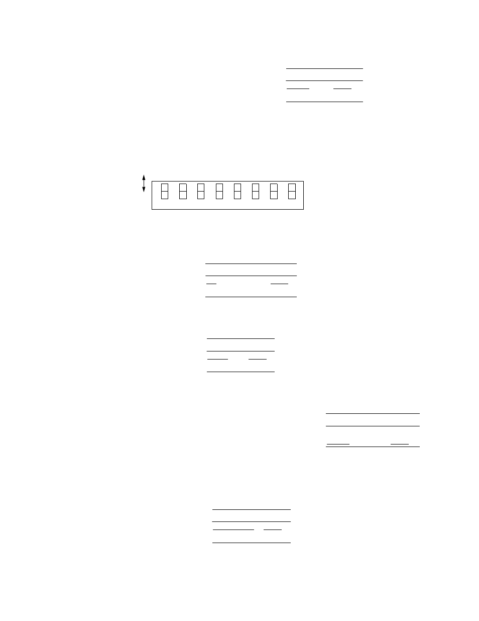
Configuration
Switch S2
Switch S2 (Figure 2-3) configures the antistream timer, V.54 loop, circuit
assurance, loop mode, supervisory port rate, and NMS port rate.
Antistream Timer
Switch S2-1 is
used to set the
Antistream Timer
as shown in
Table 2-8.
V.54 Loop Detection
Switch S2-2 is
used to enable
V.54 loop
detection as shown
in Table 2-9.
Circuit Assurance
Switch S2-3 selects whether the CTS control lead
responds to the data signal from the network as
shown in Table 2-10. When Circuit Assurance is On
and the unit is receiving idle code (i.e., DCD is Off),
the 4051 turns the CTS lead off. When Circuit
Assurance is turned off, the state of the CTS control lead is not affected by the
data signal from the network.
Loop Mode
Switch S2-4 is
used to select the
loopback method
as shown in
Table 2-11.
Table 2-7 DTE Alarm
DTE Alarm
S1-8
Disable
Down
Enable
Up
Figure 2-3 Switch S2
7
6
5
4
3
2
1
Do
wn
Up
8
An
ti
st
re
a
m
V
.5
4
Loop
Ci
rc
ui
t
NMS
NMS
Ti
m
er
En
abl
e
Po
rt
R
a
te
Po
rt
R
a
te
S
uper
v
is
o
ry
Po
rt
R
a
te
As
su
ra
n
c
e
Lo
op
Mo
d
e
S
uper
v
is
o
ry
Po
rt
R
a
te
Switch
S2
Table 2-8 Antistream Timer
Antistream Timer S2-1
Off
Down
30 Seconds
Up
Table 2-9 V.54 Loop Detection
V.54 Loop
S2-2
Enable
Down
Disable
Up
Table 2-10 Circuit Assurance
Circuit Assurance S2-3
Enable
Up
Disable
Down
Table 2-11 Loop Mode
Loop Mode
S2-4
Bidirectional
Down
Unidirectional
Up