Users manual, Mc100 – Watson-Marlow MC100 User Manual
Page 20
Users Manual
MC100
MC100 Users Manual Profibus DP - rev 4
Rev. 4
Page 20 of 40
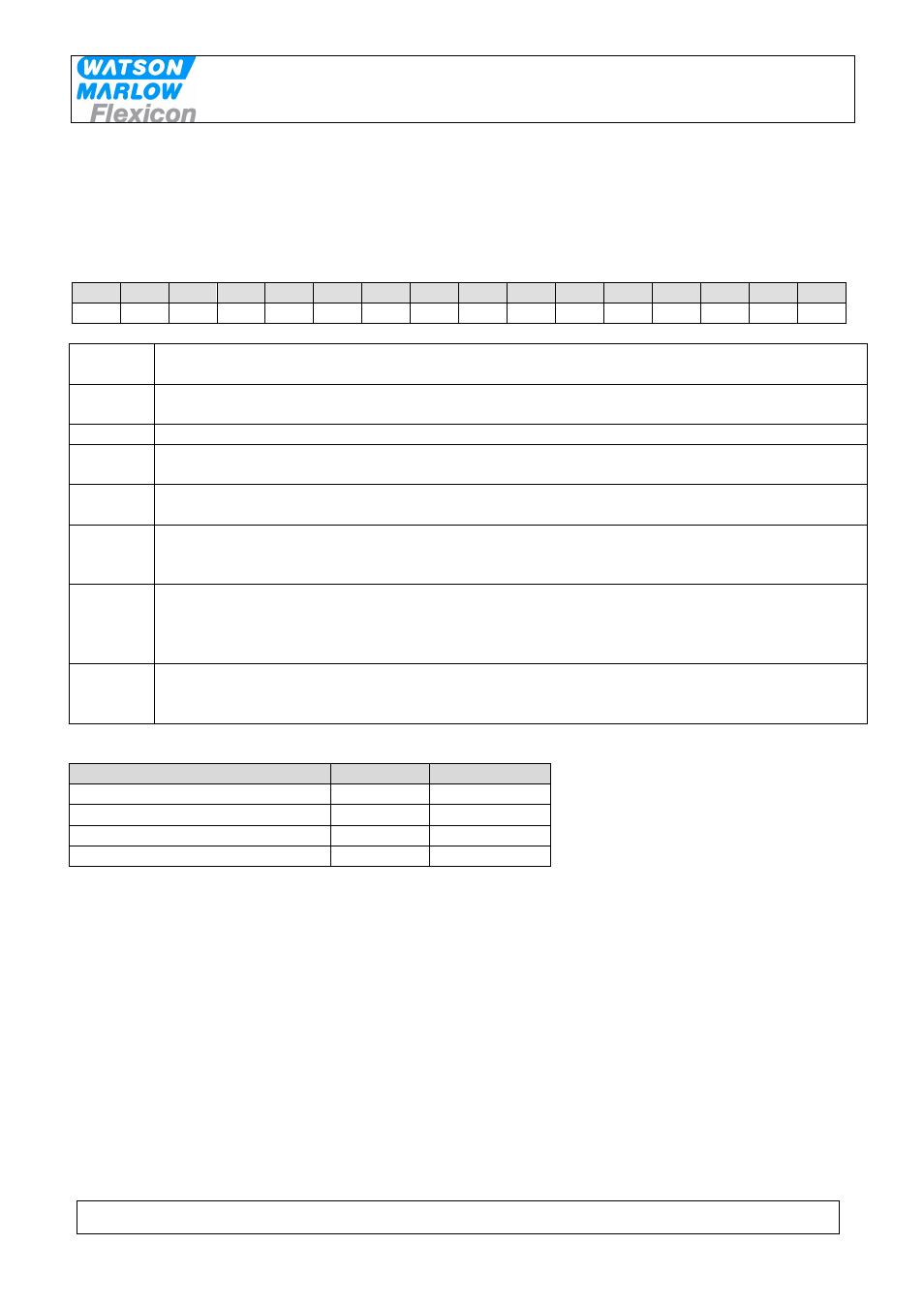
7.1.2 Process control bits – word 0
(PLC
MC100)
Word 0 (2 bytes) is allocated for MC100 control bits as shown below.
Word 0
15
14
13
12
11
10
9
8
7
6
5
4
3
2
1
0
B1.7 B1.6 B1.5 B1.4 B1.3 B1.2 B1.1 B1.0 B0.7 B0.6 B0.5 B0.4 B0.3 B0.2 B0.1 B0.0
B0.0-4:
Sets the active pump number
B0.5-7
Reserved for future use
B1.0:
Mode bit 0; please see below
B1.1:
Mode bit 1; please see below
B1.2-4
Reserved for future use
B1.5
Alarm reset: will reset lowest alarm or warning number. To reset more alarms/warnings
B1.5 must be reset to 0 and then raised to 1 again for each alarm/warning.
B1.6
Rescan the FlexNet for pumps. The FlexNet is scanned for pumps and a new table of the
attached pumps are written in the MC100.
NB. This will result in a reset of all the attached pumps.
B1.7
Total reset of MC100.
NB. This will result in a reset of all the attached pumps to default values.
Modes selected by mode bit 0 and 1:
MC100 working modes:
Mode bit 0
Mode bit 1
Individual
1
0
Parallel
0
1
Serial
1
1
Na
0
0
Individual mode
When selected the attached pumps are operated individually. I.e.
volumes; dispense signals; calibration values etc. has to be sent to
each pump.
Parallel mode
Parallel mode requires that all pumps not disabled are of the same
type, i.e. PD12 or PD22 or GD30.
In parallel mode the virtual pump 0 is used to hold common
parameters for all the enabled pumps.
In parallel mode the common data are:
• Volume
• Pump speed
• Acceleration
• Tube size
• Density
If parameters are sent to a pump different from pump 0, there is