Sequence of operations, Technical guide vavbox controller 18, Damper control – WattMaster VAVBOX User Manual
Page 18: Table 3: relay staging - unoccupied mode
Technical Guide
VAVBOX Controller
18
is received the damper will then move to its Nite/Reheat minimum po-
sition. If check for main fan status has not been selected, the series box
fan will only activate and run when it is in Space Heating mode. When
in Space Heating mode the damper will move to its Nite/Reheat mini-
mum position. When in Supply Air Heating mode the damper will modu-
late to maintain the Unoccupied Heating setpoint.
In all cases, before the series box fan can be activated, the air damper is
driven fully closed and held that way for 30 seconds to make sure the
series box fan hasn’t inadvertently started to spin backwards. Once the
series box fan starts, it waits an additional 10 seconds to allow the fan
to spin up before it starts to open the damper and introduce airflow from
the HVAC unit fan.
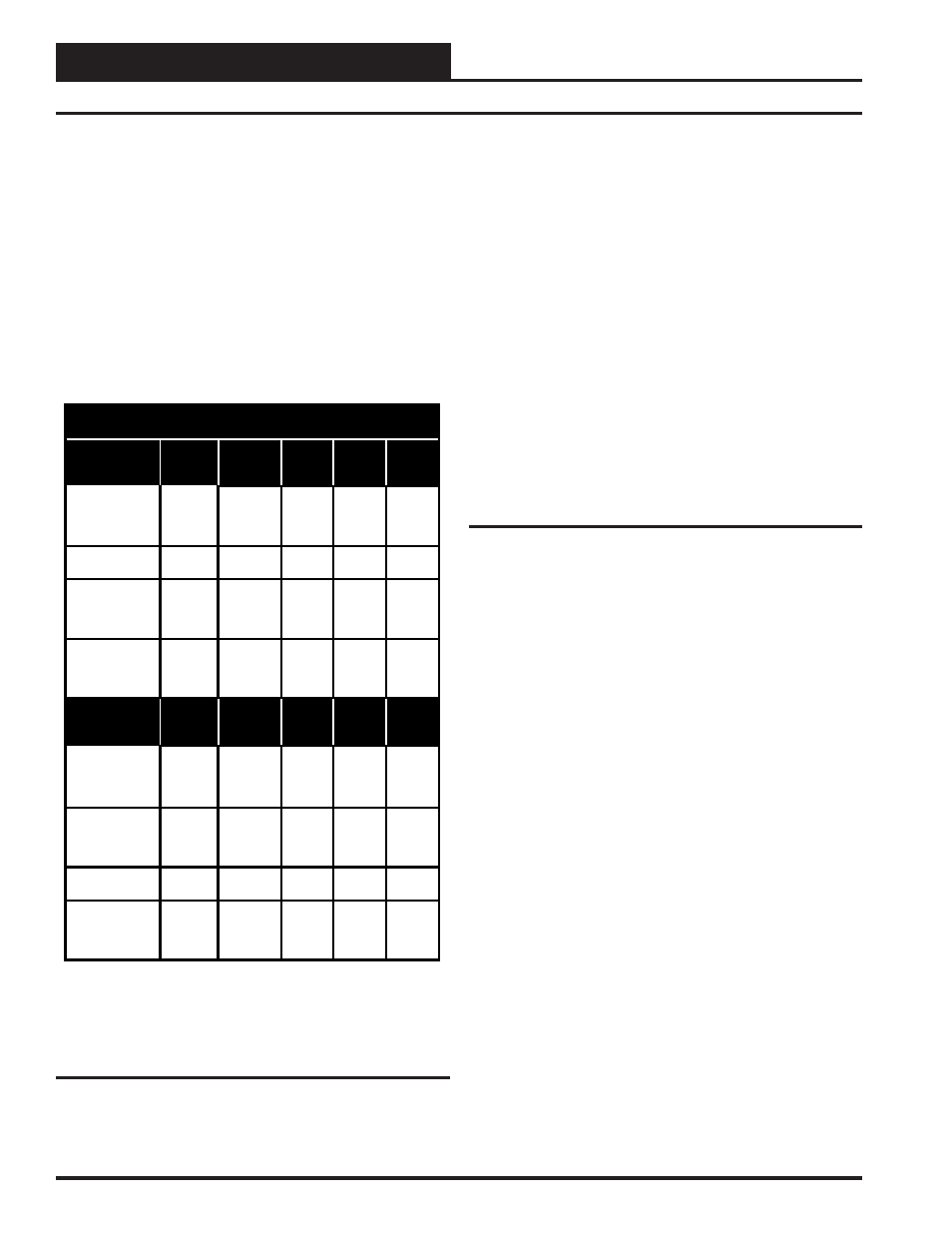
Box Fan Relay & Reheat Relay Staging
Unoccupied Mode
Relays Stage
On At
Series
Fan
Parallel
Fan
Heat
Stage
1
Heat
Stage
2
Heat
Stage
3
+0.5 ºF
Above Box
Heat
Setpoint
X
See
Note
1
X
At Box Heat
Setpoint
X
-1.0 ºF
Below Box
Heat
Setpoint
X
-2.0 ºF
Below Box
Heat
Setpoint
X
Relays Stage
Off At
Series
Fan
Parallel
Fan
Heat
Stage
1
Heat
Stage
2
Heat
Stage
3
+1.0 ºF
Above Box
Heat
Setpoint
X
See
Note
1
X
+1.0 ºF
Above Box
Heat
Setpoint
X
At Box Heat
Setpoint
X
-1.0 ºF
Below Box
Heat
Setpoint
X
Notes:
1.) If check for m ain fan status is selected the series fan will activate
anytime the HVAC unit fan is operating.
Table 3: Relay Staging - Unoccupied Mode
Parallel Flow Fan Terminals
If the VAVBOX Controller has been configured as a Parallel Fan Pow-
ered terminal unit, the Parallel fan will run continuously when the
VAVBOX controller is in the Space Heating mode no matter whether
check for main fan status has been selected or not. At all other times,
the fan will only activate if the damper/airflow is below a user defined
low limit setting. This causes it to be used as a make-up air source.
When the damper/airflow rises 15% above the low limit setpoint, the
fan will be deactivated if there are no heating stages active, and no
space demand exists.
If check for main fan status is selected the damper will remain in the
closed position until the HVAC unit controller is broadcasting that the
HVAC unit fan is operating, regardless of whether it is calling for heat
or not. The damper will be held at the closed position until the main fan
status broadcast is received. Once the broadcast is received the damper
will then move to its Nite/Reheat minimum position. If check for main
fan status has not been selected, the damper will stay in the closed po-
sition until Space Heating mode is initiated. When in Space Heating
mode the damper will move to its Nite/Reheat minimum position. When
in Supply Air Heating mode the damper will modulate to maintain the
Unoccupied Heating setpoint.
Damper Control
The damper position is calculated by the mode and demand from the
space sensor. Included in this calculation is an Integral function. This
prevents the damper/airflow from stagnating at a position somewhere
above the setpoint because the supply air temperature or duct pressure
isn’t quite enough to satisfy the space at the currently calculated pro-
portional position. The Integral causes the calculation to keep adding a
small amount of the proportional error back into the damper/airflow
position each time a new position is calculated. The amount the Integral
adds back in is user adjustable. This value is presented as a number
between 0.0 and 10.0. That means that if the integral is less than 1.0,
you are adding a percentage, from 0 to 100% of the error back into the
calculation. If you increase the Integral above 1.0, you are adding more
than 100% back in.
With just proportional control, a 2 ºF error would cause a 50% increase
in damper/airflow if the Integral is not included. (2 °F is half of the 4 ºF
Proportional Window)
If you had set the Integral to 1.0, the calculation would add 2% to the
current damper/airflow calculation each time. The calculation occurs
once every 10 seconds, so it would take a little over 4 minutes to reach
the programmed 100% maximum.
Sequence Of Operations