Troubleshooting, Table 4: scan led blink codes – WattMaster VAVBOX User Manual
Page 21
VAVBOX Controller
Technical Guide
21
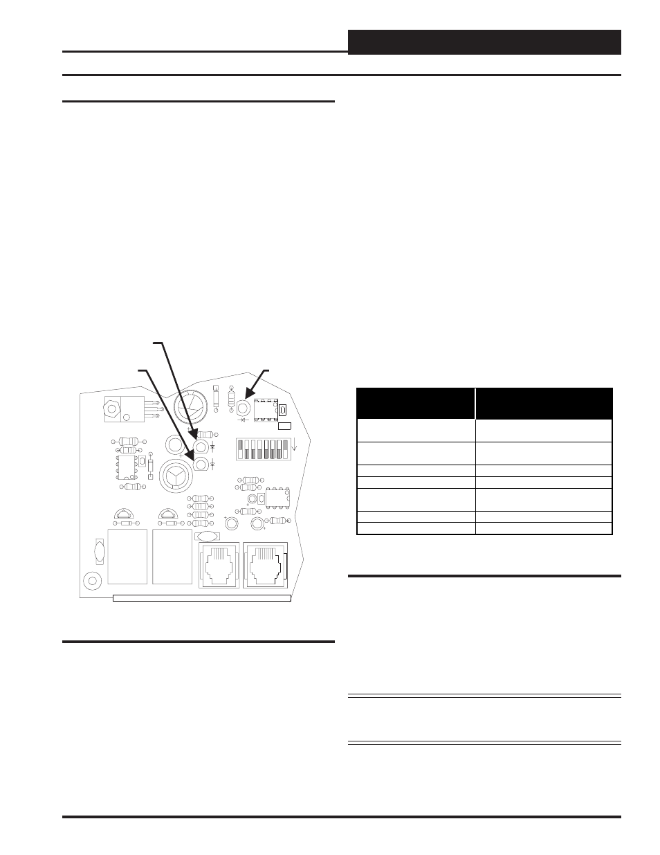
Using LED’s To Verify Operation
The VAVBOX controller is equipped with LEDs that can be used as
very powerful troubleshooting tools. The VAVBOX controller board
has three LEDs. Two of these LEDs are used in troubleshooting. See
Figure 12 for the LED locations. The LEDs and their uses are as fol-
lows:
“REC”
This LED will light up to indicate system communications.
“PWR”
This LED will light up to indicate that 24 VAC power has been applied
to the controller.
“SCAN”
This is the diagnostic blink code LED. It will light up and blink out
diagnostic codes.
CX6
SW1
U10
75176
EXPANSION
Q3
Q2
D3
VR1
7824
R17
R16
U7
C7
R15
POWER
R21
D4
R26
LD3
L1
SCAN
REC
R12
C6
R11
TOKEN
NET
LD2
32
R14
R13
R100
LD1
C5
D1
K1
V2
K2
D2
ACTUATO
R
R10
R9
PJ2
V1
C4
CX10
8
16
2
4
ADDRESS
ADD
1
U6
PJ1
C3
R8
“SCAN”
Diagnostics LED
“REC” LED
“PWR” LED
Figure 11: LED Locations
“REC” LED Operations
When the controller is communicating this LED will flicker. If it does
not flicker check the MiniLink and/or CommLink that is connected to
the Power/Comm board which connects to your VAVBOX controller
and make sure the MiniLink and/or CommLink is powered up and prop-
erly connected to the Power/Comm board.
“PWR” LED Operations
When the WMVAV Controller is powered up the “PWR” LED should
light up and stay on continuously. If it does not light up, check to be
sure that the modular connector is connected to the board, that the con-
nections are tight and the tab is locked on the connector. Be sure power
is connected and turned on to the Power/Comm board and that the modu-
lar cable connector is securely connected. If after making all these checks
the “PWR” LED does not light up, the board is probably defective.
“SCAN” LED Operations
As previously described when the board is first powered up the LED
will do the following:
•
Flashes Once
•
Off for 5 seconds
•
SCAN LED blinks the board address
(Address 14 = 14 blinks)
•
5 second pause
•
20 second time delay - LED blinks 20 times
•
LED blinks slowly as damper moves towards the open
position. The LED blinks fast as the damper moves
towards the closed position.
After the above steps the status code is repeatedly blinked every 10
seconds to indicate controller status. The status blink codes are listed in
the following table in order of priority.
:
LED Blinks This
Number Of Times
Blink Code
Description
1
Normal Operation. No Alarm
Conditions Exist
2 Push-button
Override
Or
Group Override Is Active
3 Communication
Failure
4 Bad
Airflow
Sensor
5 Bad
or
Missing
Space Sensor
6 Damper
Failure
7
Damper Feedback Failure
Table 4: SCAN LED Blink Codes
Only the highest priority failure code will be shown. You must correct
the highest priority alarm before other problems will be indicated.
If the “SCAN” LED does not operate as indicated above, first check
the address switch setting. See Figure 10 for correct address switch
setting procedures. If the address switch setting is correct and the
“SCAN” LED still does not behave as indicated above contact Watt-
Master Controls Technical support.
Note: Power to the controller being addressed must always
be cycled after changing address switch settings in or-
der for the changes to take effect.
Troubleshooting