Multidrop, dual channel, v-mode configuration, Prepare the fibre optical network – Westermo ODW-720-F2 User Manual
Page 9
9
6651-2235
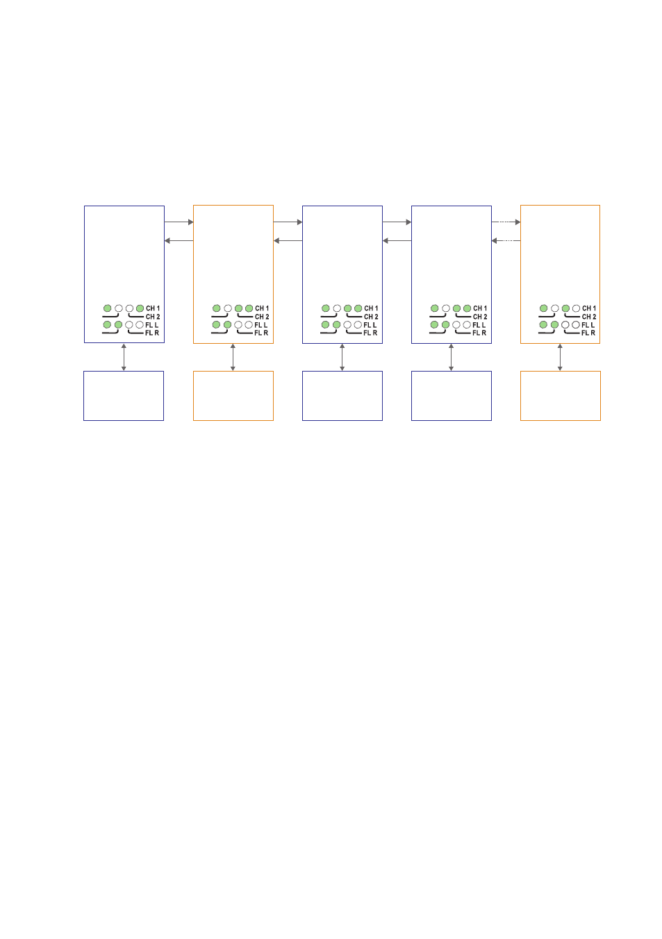
Multidrop, dual channel, V-mode configuration
In dual channel mode it is possible to use two separate data streams in a single ODW-
720 network. However, all ODW-720’s must be set to the same speed and data format.
This, of course, limits the number of possible applications for a dual channel network.
In V-mode an ODW-720 network will behave as a 4-wire bus. Where the first ODW-720
(leftmost in the picture below) will able to communicate in full duplex with any other
unit, but other units are incapable of communicating with each other.
RX2
TX2
Primary – End Unit
S1: 8 ON
S2: 3 ON
S2: 4 OFF
S1: 8 OFF
S2: 3 OFF
S2: 4 ON
S1: 8 ON
S2: 3 OFF
S2: 4 OFF
End Unit
S1: 8 ON
S2: 3 ON
S2: 4 ON
Device 1
Communicates
with device 3 and 4 on
the primary data channel
Device 2
Communicates
with device 5 on the
secondary data channel
Device 3
Communicates
with device 1 on the
primary data channel
Device 5
Communicates
with device 2 on the
secondary data channel
TX1
RX1
RX2
TX2
TX1
RX1
RX2
TX2
RS-232
RS-232
RS-232
Fibre
pair
Fibre
pair
Fibre
pair
RS-232
TX1
RX1
RX2
TX2
TX1
RX1
PWR
FP
TD
RD
PWR
FP
TD
RD
PWR
FP
TD
RD
S1: 8 ON
S2: 3 OFF
S2: 4 OFF
Device 4
Communicates
with device 1 on the
primary data channel
RS-232
Fibre
pair
RX2
TX2
TX1
RX1
PWR
FP
TD
RD
PWR
FP
TD
RD
Prepare the fibre optical network
• Configure all ODW-720 units for the correct speed and data format using DIP-
switches S1:1 – S1:7. Again, notice that all ODW-720’s must be set to the same speed
and data format.
• The first and last ODW-720 units must be configured as Multidrop end units by
setting DIP-switch S2:3 to the ON position (End units only have one fibre pair
each and must know that this is a fact).
• All ODW-720 units that are to use the primary data channel (“blue” units in the
picture above) must have DIP-switch S2:4 set to the OFF position. Units that are
to use the secondary data channel (“orange” units in the picture above) must have
DIP-switch S2:4 set to the ON position.
• The first ODW-720 unit using the secondary data channel (second from left in
the picture above) must have DIP-switch S1:8 set to the OFF position (Y-mode).
The reason for this is that the data will be sent in the wrong direction if this unit
is also set for V-mode.
• Set DIP-switch S1:8 in the ON position (V-mode) on all other ODW-720 units.
• Set DIP-switch S2:6 as desired. See page 33 “Status port” for more information.
• Verify that DIP-switches S2:1, S2:2, S2:5 and S2:8 are set in the OFF position.
• Connect the fibre pairs between the units. Always connect CH 1 from one unit to
CH 2 on the next unit as shown in the picture above.