Redundant ring configuration – Westermo ODW-710-F2 User Manual
Page 19
19
6651-2211
Prepare the PROFIBUS units
… Configure PROFIBUS network, with master and slaves. Check that the application is
running correctly with the electrical PROFIBUS network.
Note: In an ODW-710-F2 fibre optic network there will be some additional processing
delays that do not exist in an electrical bus. It is possible that the PROFIBUS application
must be adjusted to accommodate these delays if using many ODW-710-F2 units in a large
network.
See page 22 “Calculating system processing delay” for more information on how to deter-
mine the overall system delay time.
Prepare the fibre optical network
… One, and only one, of the ODW-710-F2 units must be configured as a ring focal point
by setting DIP-switch S2:3 to the ON position. (The ring focal point acts as a logical
end point in the optical fibre ring, thus forming a bus type of structure)
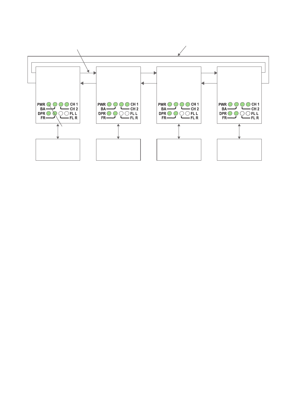
… Connect the fibre pairs between the units. Always connect CH 1 from one unit to
CH 2 on the next unit as shown in the picture above.
… Connect the power supply to all units and verify that all fibre links become active.
(CH 1 and CH 2 LED’s are on, FL L and FL R LED’s are off).
… Connect the PROFIBUS master and slaves to the corresponding ODW-710-F2 unit.
Note: It is not required that the PROFIBUS master is connected to the ODW-710-F2
ring focal point, but it makes sense if one wishes to keep the installation “tidy” and easy to
maintain.
… The network is now up and running.
Redundant ring configuration
PWR LED
Flashing to
indicate master
RX2
TX2
Focal Point
S2: 3 ON
PROFIBUS
Master
TX1
RX1
RX2
TX2
Ring Member
Ring Member
Ring Member
TX1
RX1
RX2
TX2
TX1
RX1
RX2
TX2
TX1
RX1
PROFIBUS
Slave
PROFIBUS
Slave
PROFIBUS
Slave
Redundant fibre pair.
Not used under normal operation.
Fibre pair used
to carry data.