Calculating system processing delay – Westermo ODW-710-F2 User Manual
Page 21
21
6651-2211
Calculating system processing delay
Data exchange between a PROFIBUS DP master and slave via ODW-710-F2 fibre optic
link will be delayed due to the length of the optical fibre and the signal processing within
the ODW-710-F2. The signal processing delay is dependent on the data rate, and the
fibre delay is dependent on the total length of the optical fibre. The additional time
resulting from the optical fibre and ODW-710-F2 is the Overall system delay.
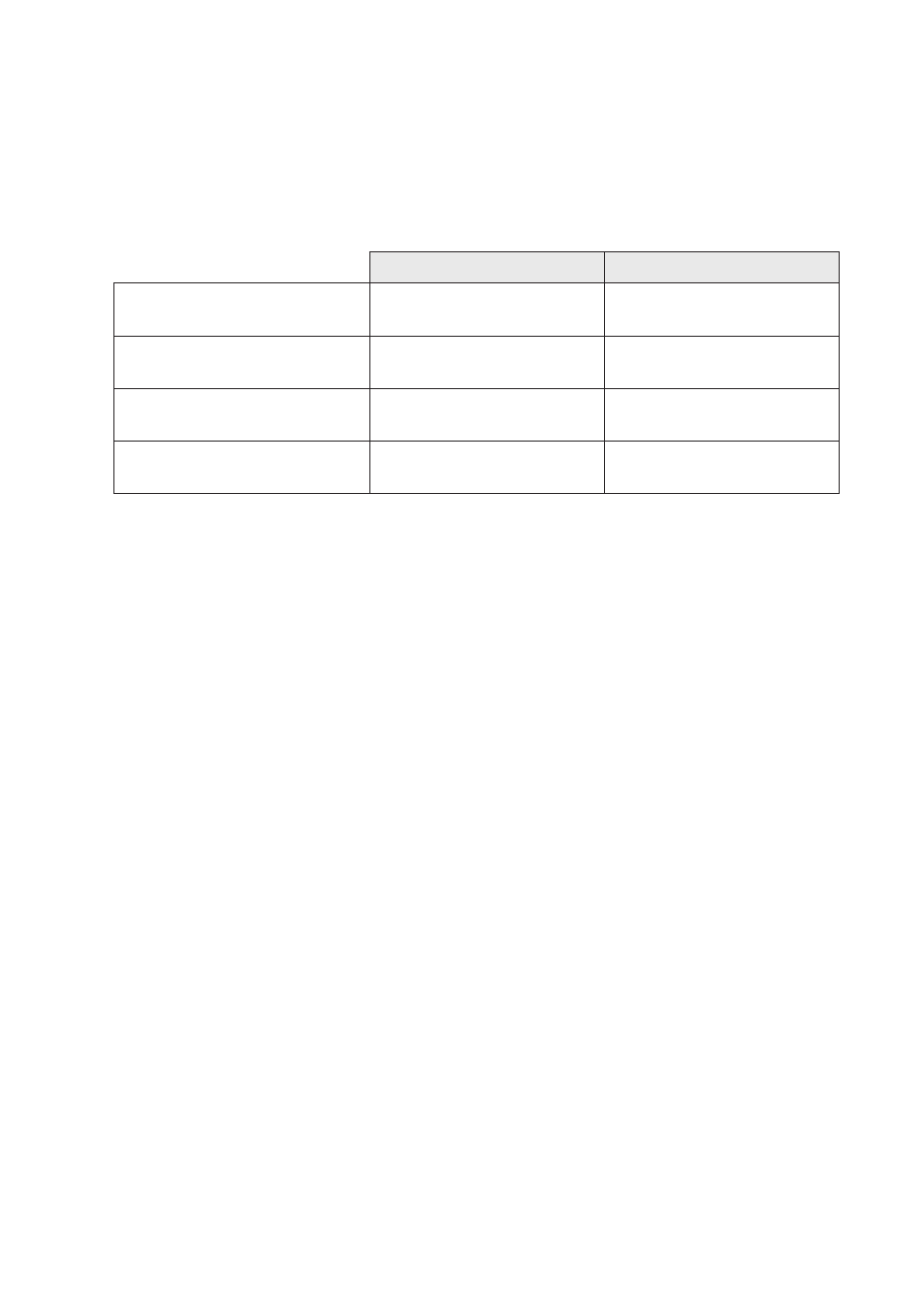
Delay @ < 1.5 Mbit/s
Delay @ 3 to 12 Mbit/s
Optical fibre length delay
(typical)
5 µs/km
5 µs/km
Signal processing, electrical to
fibre (max)
1 tbit + 1 µs
9 tbit + 1 µs
Signal processing, fibre to
electrical (max)
0.3 µs
0.3 µs
Signal processing, fibre to fibre
(max)
1.3 µs
1.3 µs
Note tbit = 1 / Baud rate (Baud rate in bit/s)
Example
One PROFIBUS DP master and 11 slaves with data rate 12 Mbit/s. 12 ODW-710-F2
units with a total fibre length of 40 km. A data frame sent from the master to a slave
at the farthest end of the optical network.
1. Optical fibre length delay: The total optical fibre length delay.
40 x 5 µs = 200 µs
2. Signal processing electrical to fibre: Signal processing delay
(ODW-710-F2 units connected to PROFIBUS DP master).
9 tbit + 1 µs= 9 x 0.083 µs + 1 µs x 2 = 1.1 µs
3. Signal processing fibre to electrical: Signal processing delay
(ODW-710-F2 units connected to PROFIBUS DP slave).
0.3 µs
4. Signal processing fibre to fibre: The optical repeater delay x Number of optical
repeaters (excluding the ODW-710-F2 units connected to PROFIBUS DP master and
addressed slave).
(12 – 2) x 1.3 µs = 13 µs.
5. The system delay is calculated by summing the delays in item 1 to 4 above:
200 µs + 1.1 µs + 0.3 µs + 13 µs = 214 µs