Location of interface ports and led’s, Ethernet connection tx (2 ports), Power connection – Westermo DDW-142-485 User Manual
Page 12
12
6642-22511
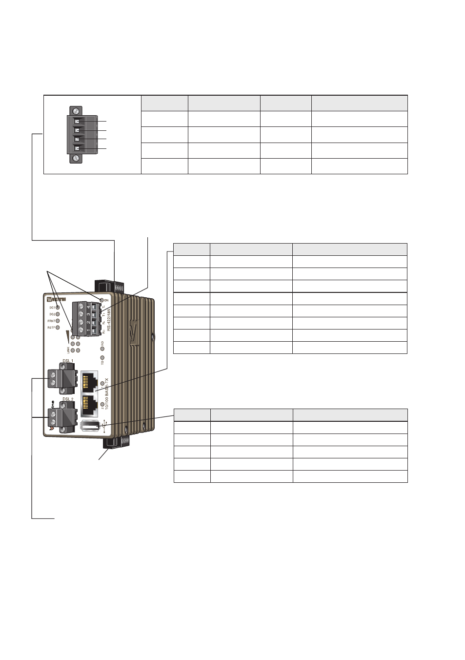
Location of interface ports and LED’s
LED Indicators
(for details
see page 15)
RS-422/485
(for details see page 9 and 14)
I/O connection
(for details see
page 11 and 14)
SHDSL connection (for details see page 11 and 14)
Ethernet connection TX (2 ports)
(for more details see also page 10)
Position
Direction*
Description
No.1
In/Out
Transmitted/Received data
No. 2
In/Out
Transmitted/Received data
No. 3
In/Out
Transmitted/Received data
No. 4
–
Not Connected
No. 5
–
Not Connected
No. 6
In/Out
Transmitted/Received data
No. 7
–
Not Connected
No. 8
–
Not Connected
* Direction relative this unit.
USB
(for more details see also page 10)
Position
Direction*
Description
No.1
Out
VBUS
No. 2
In/Out
D–
No. 3
In/Out
D+
No. 4
Out
GND
Shield
–
Connected to protective earth
* Direction relative this unit.
Power connection
(for more details see also page 10)
1
2
3
4
4-position
Product marking
Direction
Description
No. 1
+DC1
Input
Supply voltage input DC1
No. 2
+DC2
Input
Supply voltage input DC2
No. 3
-COM
Input
Common
No. 4
-COM
Input
Common
This unit supports redundant power connection. The positive inputs are +DC1 and +DC2, the negative input for
both supplies are –COM. Connect the primary voltage (e.g. +24 VDC) to the +DC1 pin and return to one of the
–COM pins on the power input.