Connections – Westermo DR-250 User Manual
Page 11
11
6622-2211
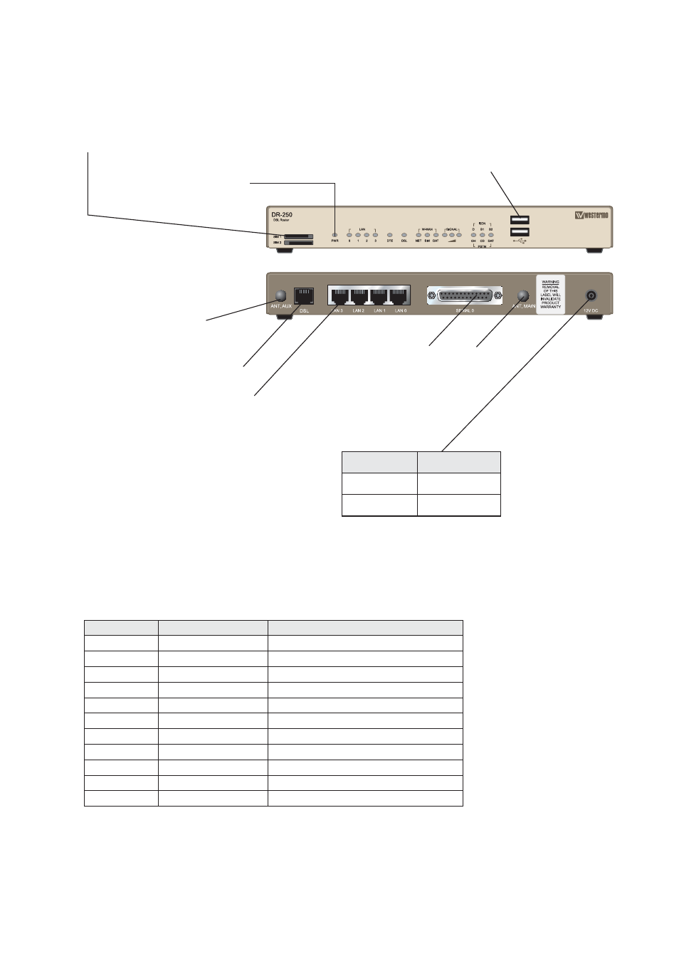
SIM Card Sockets
The two sockets at the left side of the front panel are for the GSM SIM card(s)
that you will receive from your service providers. Details of how to insert these
correctly are given on page 13.
Antenna
interface
Connections
Power interface cord
Cable
Description
Black
– VDC
Red
+ VDC
Ethernet interface
Ethernet interface
RS-232
interface**
USB Host Connectors*
LED Indicators
(for details
see next page)
*
The USB host connectors may be used
to connect compatible USB 2.0 client
devices such as memory sticks, serial
adapters, etc. Note that the total cur-
rent available to power USB devices is
collectively 0.5A (i.e. for both ports).
**
RS-232 D-sub
25-position
Direction
Description
No. 2
In
Transmit Data (TD)
No. 3
Out
Receive Data (RD)
No. 4
In
Request To Send (RTS )
No. 5
Out
Clear To Send (CTS)
No. 6
Out
Data Set Ready (DSR)
No. 7
–
Signal ground (SG)
No. 8
Out
Data Carrier Detect (DCD) )
No. 15
In
Transmitter Clock (TxC)
No. 17
Out
Receiver Clock (RxC)
No. 20
In
Data Terminal Ready (DTR)
No. 24
In
External Transmitter Clock (ETC)
Antenna
interface