Safety control drawing – Westermo Lynx-x08-F2G-S2-EX User Manual
Page 16
16
6643-22701
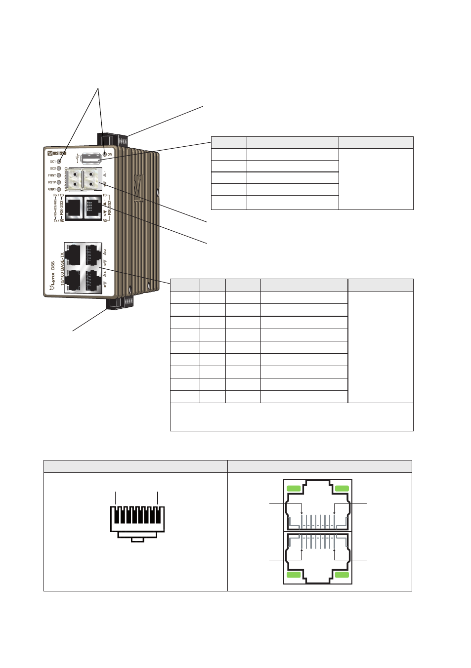
LED Indicators (for details see page 16)
Power connection (for details see page 9 and 15)
SFP transceivers (for details see page 11)
RS-232, RS-422/485 (for details see page 10 and 13)
I/O connection
(for details see page 11 and 15)
RJ-45 connector (Front view)
Male
Female
Pin 8
Pin 1
Pin 1
Pin 8
Pin 8
Pin 1
Safety control drawing
Location of interface ports and LED’s
Ethernet connection TX (4 ports)
Position Signale Direction Description
Input/output values
No.1
TD+
In/Out Transmitted/Received data
Per port:
U = ± 1 V (4μV/s)
I = ± 20 mA
Data rate:
10/100 Mbit/s
No. 2
TD–
In/Out Transmitted/Received data
No. 3
RD+
In/Out Transmitted/Received data
No. 4
–
Not Connected
No. 5
–
Not Connected
No. 6
RD–
In/Out Transmitted/Received data
No. 7
–
Not Connected
No. 8
–
Not Connected
Shield
Connected to PE
Galvanically isolated via signal transformers and capacitively isolated to
GND/PE through a 2kV 1000pF capacitor.
See user manual for proven transient protection.
USB
Position Direction* / description
Output values
1
Out / VBUS
U
out
= 5 VDC max
I
out
= 500 mA max
2
In/out / D–
3
In/out / D+
4
GND
Shield
PE