Transmission range (interface 2), Hints – Westermo MA-47 User Manual
Page 6
13
6047-2002
Transmission range (interface 2)
Use twisted pair cable. Max transmission range 1200 m.
(cable specifications 0.3mm
2
and capacitance 42pF/m).
The transmission range will increase if a cable with lower capacitance and larger
diameter is used.
Use shielded cable in heavy industrial environments.
Hints
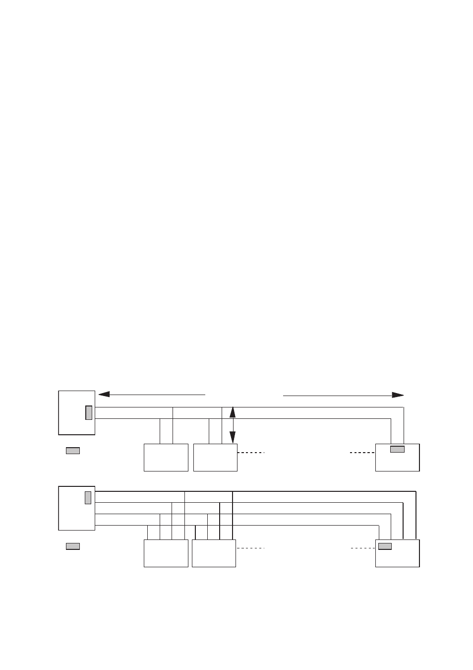
The MA-47 uses the RS-422/485 interface. RS-422/485 was designed for multidrop appli-
cations. When a system is installed it should form a bus structure (see diagrams). Star
shaped networks should never be created, there are other Westermo products designed
to work in star net applications. To install correctly, an RS-422/485 network should be
terminated at the correct points. The recommendation is to terminate the receiver on
the master unit and the final bus slave unit. See diagrams for details of how this is done
with RS-485 (2 wire) and RS-422 (4 wire).
The line transmitter used in the MA-47 is activated by data received on the RS-232
interface, unlike conventional converters that rely on a control signal (e.g. RTS).
If any problems do occur on set up of the MA-47, the LED’s will be helpful.
• PWR: The unit has power.
• RD:
Data received on the RS-422/485 interface.
• DCD: Follows RD in two wire operation. Always active for four wire.
• CTS:
Follows RTS
• RTS:
Status of RTS from the RS-232 interface
• TD:
Data received on RS-232 interface
=Termination
Max 32 connections
Max 1200 metres
Max 0.3 metre
=Termination
Max 32 connections
A
B
A
B
A
B
A
B
A’
B’
A
B
B’ A’
A’
B
B
A
B’ A’ B A
A
B’
N.B. R+/R–, T+/T– definitations are not standard, it can help to shift A and B
if the unit does not work.