Interface specifications, Connector p3 – Westermo RV-07B User Manual
Page 7
7
6130-2200
Interface specifications
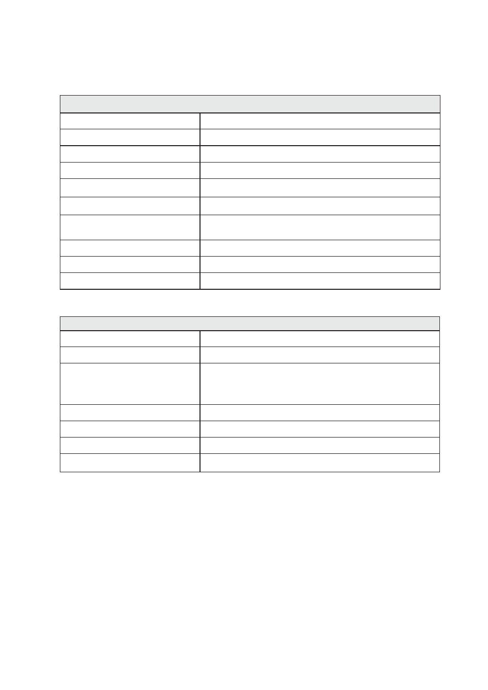
Connector P3
Power RV-07B, External DC Power
Rated voltage
Depending on which card inserted in the slot.
Operating voltage
Depending on which card inserted in the slot.
Rated frequency
Depending on which card inserted in the slot.
Power consumption
Depending on which card inserted in the slot.
Polarity
Polarity dependent
Redundant power input
No
Isolation to
All other ports 2 kVrms 50 Hz 1 min (GND excluded)
GND 500 kVrms 50 Hz 1 min
Connection
Detachable screw terminal
Connector size
0.2 – 2.5 mm
2
(AWG 24 – 12)
Shielded cable
Not required
Connector P3 populated with 16 TR-36B modems
Power TR-36B*
Rated voltage
12 to 48 VDC
Operating voltage
10 to 60 VDC
Rated current
2,0 A @ 12VDC
1,0 A @ 24VDC
0,64 A @ 48VDC
Rated frequency
DC
Power consumption
35 W
Startup current
3,6 Apeak
Polarity
Polarity dependent
* Maximum wire length to external power supply < 10.
External supply current capability for proper startup.
To minimise the risk of interference, a shielded cable is recommended when the cable is located inside 3 m
boundary to the rails and connected to this port.
The cable shield should be properly connected (360°) to an earthing point within 1 m from this port. This earth-
ing point should have a low impedance connection to the conductive enclosure of the apparatus cabinet, or
similar, where the unit is built-in. This conductive enclosure should be connected to the earthing system of an
installation and may be directly connected to the protective earth.