Westermo Viper-x12-p8 User Manual
Page 12
Advertising
12
6641-2252
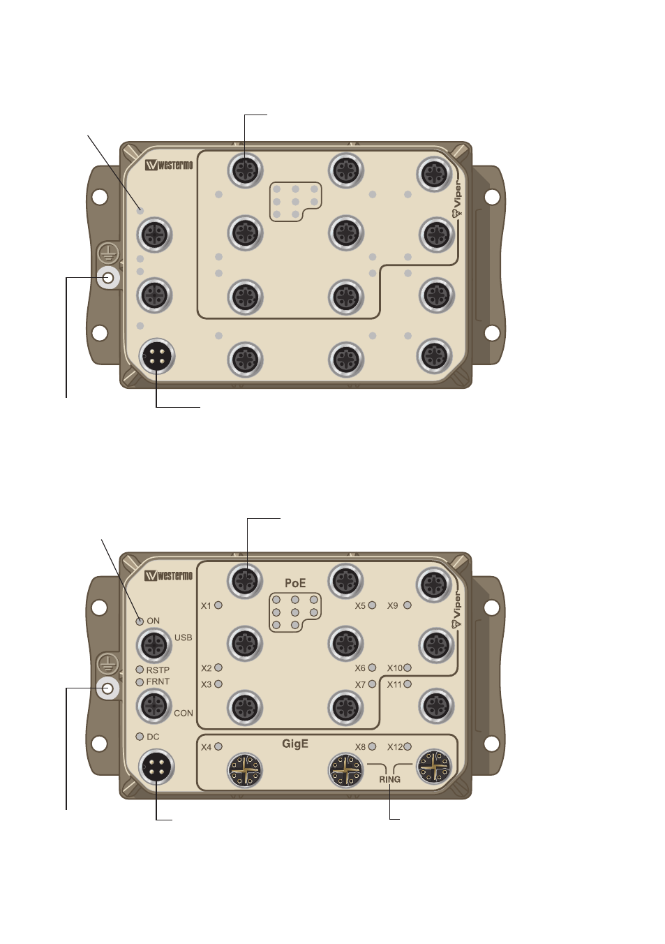
Location of interface ports and LED’s
Viper-112-P8 and Viper-212-P8
Location of interface ports and LED’s
Viper-112-T3G-P8 and Viper-212-T3G-P8
DC
ON
USB
CON
RSTP
FRNT
X1
PoE
X5
X9
X6
X10
X7
X11
X8
X12
X2
X3
X4
Ethernet connection TX (X1 – X12)
(for details see page 8 and 11)
Power connection
for details see page 8 and 11)
LED indicators
(for details see page 13)
Earth
connection
Ethernet connection TX (X1 – X12)
(for details see page 8 and 11)
LED indicators
(for details see page 13)
Power connection
for details see page 8 and 11)
RING
Connect between these ports (X8, X12)
to get maximum performance in a ring
topology
Earth
connection
Advertising