AEC 1-Pump 1-Station Controller User Manual
Page 14
1 –Pump 1-Station Controller
Chapter 3: Installation
13 of 30
Connecting the Control Panel to Vacuum Receivers
The receiver bin-full sensor is already wired into inputs on a terminal block in the control
panel. Refer to the electrical schematic supplied in the information package.
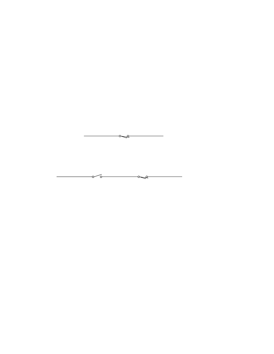
A station bypass switch can be wired into the bin-full sensor circuit as shown in Figure 1
shown below. Mount the switch near the receiver and use it to simulate a bin-full
condition. When the switch opens, the control finishes the current cycle then goes into
AutoSutdown mode.
Close the switch to restart the conveying sequence.
Note: This step is useful when servicing the receiver, clearing obstructions, or
changing materials or machine bin/silo.
Figure 1: Station Bypass Switch Diagram
A
B
Wiring without Station Bypass Switch
Bin-Full switch (LS)
N. O.
(normally open, held closed)
A1
B
A
Wiring with Station Bypass Switch
Station Bypass switch
(TS)
Off
On
Bin-Full switch
(LS)
Connecting the Control Panel to the Pump/Blower Package
Wire your single-station control panel to the motor starter coil, vaccum switch, and vent
valve on the vacuum pump or blower package. Refer to the electrical schematic enclosed
with the unit for more information.
If you purchased the optional rotary/selector switch, connect each receiver bin-full sensor
to a terminal block in the control panel. Only one material receiver can be selected at a
time. To select a receiver, turn the switch to the receiver number you want, and make the
connection to the appropriate vacuum receiver. This method is useful when filling silos
one at a time.