Connecting, Guidelines, Locating the data converter & routing the cables – Airmar T42 Temperature Sensor User Manual
Page 3: Wiring the instrument & power source
Connecting
Guidelines
CAUTION: To reduce electrical interference from other electrical
wiring and any on-board equipment with strong magnetic fields such
as radar equipment, radio transmitters, boat engines, generators,
etc., separate the cables by at least 1m (3').
CAUTION: Be careful not to tear the cable jackets when passing
them through the bulkhead(s) and other parts of the boat. Use
grommet(s) to prevent chafing.
CAUTION: Make power connections to a 12 VDC power source
that is isolated from the engine start battery(s). Voltage drops may
cause the instrument/receiver/sensor to lose information and/or
change operating mode.
CAUTION: Use a multimeter to check the polarity and the
connections to the power supply before applying power to the
sensor.
Locating the Data Converter & Routing the Cables
1. Select a convenient dry mounting location for the water-resistant
Data Converter. Locate it a minimum of 1m (3') away from the
display (see Figure 3). Position the converter so the bushings
are easily accessible. If the Data Converter will be mounted on
a vertical surface, be sure the bushings are facing downward to
avoid water seeping into the box.
2. Hold the Data Converter at the selected location and mark the
holes for the screws. Do not fasten it in place at this time.
3. Route the sensor cable from the temperature sensor to the
Data Converter. Do not fasten the cable in place at this time.
4. Route the Data Converter cable from the Data Converter to the
instrument (and power source on some installations).
Do not fasten the cable in place at this time.
Wiring the Instrument & Power Source
Some installations will connect to the power source within the
instrument. Other installations require wiring to a separate power
source located near the instrument.
1. If the instrument is connected to a power source, be sure the
power is OFF before proceeding.
2. Allowing an extra 25 cm (10") for wiring ease, cut the instrument
cable to length.
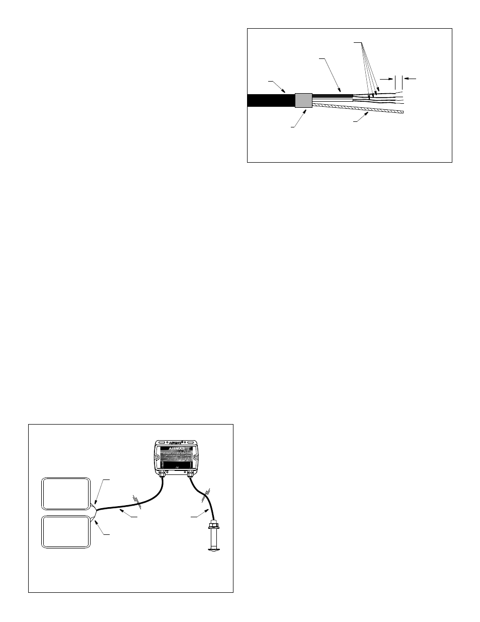
3. If the power source is separate from the instrument, strip the
cable jacket and expose the two twisted pairs of wires (see
Figure 4). Strip the outer insulation from each pair.
4. Strip 10mm (3/8") of insulation from each of the four colored
wires making up the pairs.
5. Cut off the bare wire flush with the cable jacket.
6. Protect the cable’s foil shielding from causing a short by using
heat-shrink tubing around the jacket where the wires emerge
from the cable. Be sure the tubing overlaps the wires a
minimum of 6mm (1/4").
7. Connect the wires to the instrument following the instructions in
your owner’s manual (see Figure 3). Use the color code below:
White
NMEA + A
Blue
NMEA – B
8. Connect to the power supply. It will either be within the
instrument or a separate power source. Use the color code
below:
Red
12 VDC +
Black
12 VDC –/ground
3
remove some
cable
jacket
remove
of insulation
Figure 4. Preparing the cut end of the Data Converter cable
heat-shrink
tubing
cut off
bare wire
Copyright © 2005 Airmar Technology Corp.
Figure 3. Connecting to the instrument
power
source
instrument
Copyright © 2007 Airmar Technology Corp.
red 12 VDC +
black 12 VDC –/ground
white NMEA +A
blue NMEA –B
insulation from
from colored
wires
10mm (3/8")
twisted pairs
to expose
colored wires:
blue
white
red
black
colored wires
twisted pair:
twisted pair:
and a separate power source
(some installations) (not to scale)
Data Converter
instrument
cable
sensor
cable