Airmar, Completing the installation, Maintenance & replacement – Airmar T42 Temperature Sensor User Manual
Page 4: Connecting the sensor to the data converter, Anti-fouling paint, Replacement sensor & parts
1
2
3
4
5
6
7
8
sensor
cable
bushings
temp +
temp –
blue
black
terminal function wire color
4
8
Data Converter
4
Copyright © 2005 - 2010 Airmar Technology Corp. All rights reserved.
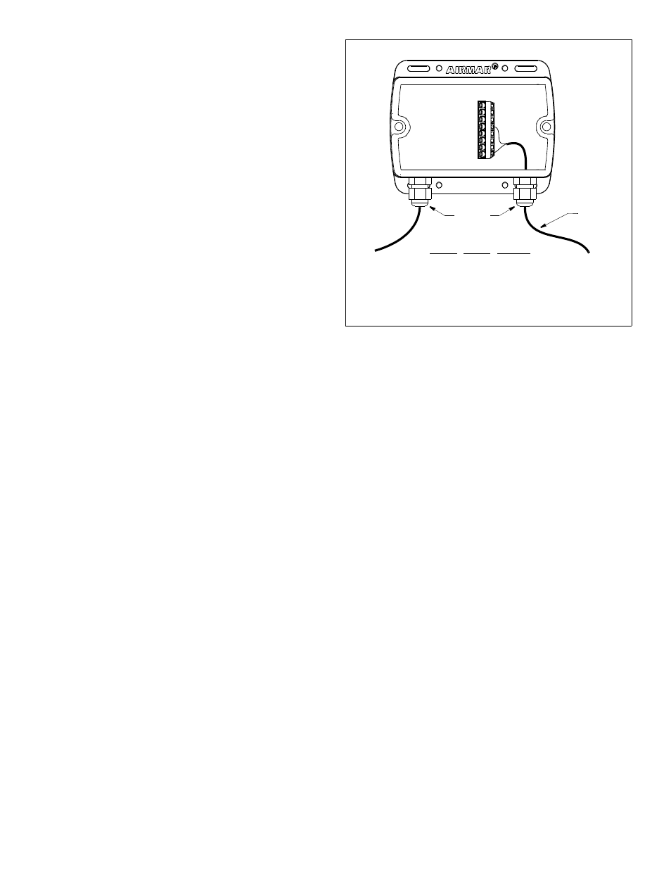
Connecting the Sensor to the Data Converter
If your sensor came with a connector, plug it into the Data
Converter. If your sensor does not have a connector, follow the
instructions below.
1. Allowing an extra 25 cm (10") for wiring ease, cut the sensor
cable to length.
2. Remove the cover of the Data Converter. Peel the tape away
from the inside and set the screws aside.
3. Push approximately 200mm (8") of the sensor cable through
the bushing of the Data Converter (see Figure 5). To ease
sliding, apply alcohol to the cable jacket.
4. Strip 60mm (2-1/2") of the outer jacket and foil shielding from
the cut end.
5. Strip 10mm (3/8") of conductor insulation from the end of each
colored wire.
6. Cut off the bare wire flush with the cable jacket.
7. Protect the cable’s foil shielding from causing a short by using
heat-shrink tubing around the jacket where the wires emerge
from the cable. The tubing must overlap the wires a minimum of
6mm (1/4").
8. From outside the Data Converter, carefully pull the sensor cable
until only 13mm (1/2") of the cable jacket remains inside the box.
9. Connect each colored wire in turn to its corresponding terminal
on the terminal block (see Figure 5). Following the color code
listed on the inside of the Data Converter cover, insert the
stripped end of the wire into the hole in the terminal and tighten
the screw using a small blade screwdriver. Be sure the stripped
end of the wire is inserted up to its insulation only. Do not
include any insulation inside the terminal. Gently tug on the wire
to ensure that it is securely fastened. Repeat this process until
all the wires are connected.
10.Arrange the wires neatly inside the Data Converter, being sure
that no bare wires are touching.
11.Hand tighten the nut on the bushing to make a water-resistant
seal.
12.Reattach the Data Converter cover with the screws supplied.
Completing the Installation
1. Using a 3mm or 1/8" drill bit, drill the holes for the screws at the
selected Data Converter mounting location.
2. Fasten the Data Converter using the four screws supplied.
3. Fasten all the cables in place.
Maintenance & Replacement
Aquatic growth can accumulate rapidly on the sensor’s surface
reducing its performance within weeks. Clean the surface with a
Scotch-Brite® scour pad and mild household detergent taking
care to avoid making scratches. If the fouling is severe, lightly wet
sand with fine grade wet/dry paper.
Anti-fouling Paint
Surfaces exposed to salt water must be coated with anti-fouling
paint. Use water-based anti-fouling paint only. Never use ketone-
based paint since ketones can attack many plastics possibly
damaging the sensor. Reapply anti-fouling paint every 6 months
or at the beginning of each boating season.
Replacement Sensor & Parts
The information needed to order a replacement sensor is printed
on the cable tag. Do not remove this tag. When ordering, specify
the part number and date. For convenient reference, record this
information at the top of page one.
Lost, broken, or worn parts should be replaced immediately.
Hull nut
02-031-3
Obtain parts from your instrument manufacturer or marine dealer.
Gemeco
Tel: 803-693-0777
(USA)
Fax: 803-693-0477
email: [email protected]
Airmar EMEA
Tel: +33.(0)2.23.52.06.48
(Europe, Middle East, Africa) Fax: +33.(0)2.23.52.06.49
email: [email protected]
AIRMAR
®
TECHNOLOGY CORPORATION
35 Meadowbrook Drive, Milford, New Hampshire 03055-4613, USA
www.airmar.com
Figure 5. Connecting the sensor to the Data Converter
Copyright © 2007 Airmar Technology Corp.
(some installations)